¶ Introduction

This Quick Start Guide to the TRIUMPH-LS contains the basic information a user new to J-Field, the field software of the TRIUMPH-LS and VICTOR-LS, needs to know to get started working quickly.
It is important that new users to J-Field read and understand the information in this manual before attempting to use J-Field. To obtain good results and RTK solutions, it is most critical to understand the RTK Verification and Validation process and settings.
More information and details are provided in the Supplemental User’s Guide to the TRIUMPH-LS. J-Field also contains its own ever-growing on-board manual with context sensitive help files for various screens. Press the hardware  (Help) button to learn more about each screen.
![]()
J-Field is rapidly being developed with new updates typically being released monthly; because of this, screenshots and features in this guide may appear differently from the latest version of J-Field. Be sure to check www.javad.com/jgnss and the user forum at support.javad.com frequently to stay current on all of the breaking news and innovative developments from JAVAD GNSS, INC. Details about new features can also be found in the Application Notes accessed from the Support menu.
Central to J-Field are four key concepts, briefly introduced here and that are discussed more fully in their respective sections:
-
Project - A user-defined job identifier with its own database file and folders for storing data
-
Page - Each Project has 10 pages that can contain points and lines and can be toggled on or off similar to CAD layers. Each Page has the option of having its own coordinate system.
-
ShapeTags - User-defined tags for points that can be assigned to create lines between points with like ShapeTags
-
Codes - Each point has a Code field to store commonly used point descriptions. Once a Code has been created, it can be recalled from the Codes Library or from the Favorite Codes list.
¶ Anatomy - Exterior of TRIUMPH-LS
¶ Top, Left and Front Faces
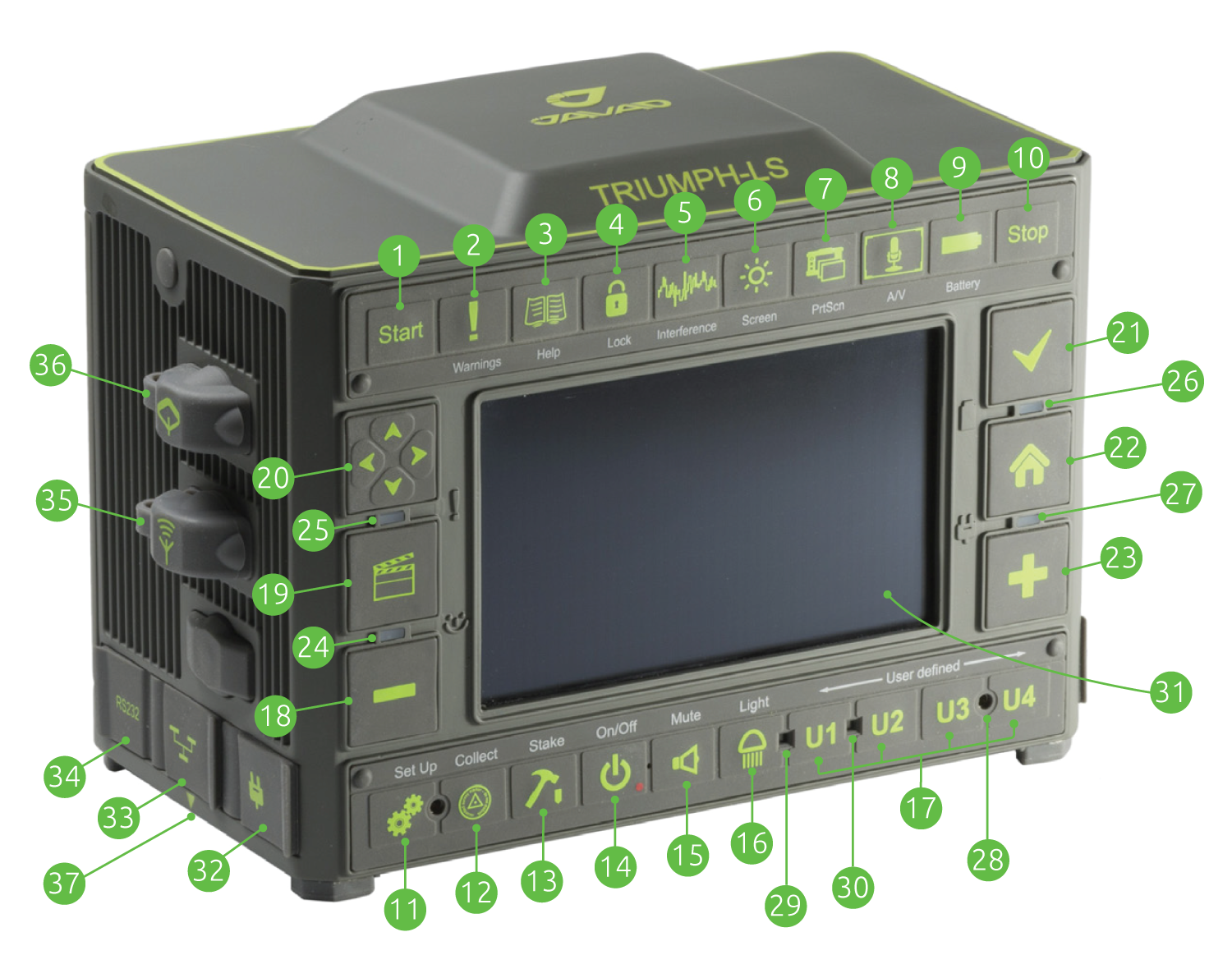
- Start - Start the collection of a point
- Warnings - Press when the warning LED is red to view warning messages
- Help - learn more about the current screen
- Lock - lock the screen to prevent accidental actions
- Interference - Spectrum analyzer to check for interference in the GNSS bands
- Screen - Cycle the screen to white or black backgrounds for better visibility in the sun
- Print Screen - Capture a screenshot
- A/V - Control sounds, volume and display brightness
- Battery - status of the battery and internal temperatures
- Stop - Stop the collection of a point
- Setup - Cycle between the Setup and Advanced Setup screens
- Collect - Cycle through the collect screens
- Stake - Cycle through the stake screens
- On/Off - Turn on the unit, hold down if the system is unresponsive
- Mute - Mute the sound
- Light - Turn on/off the flashlight
- User Defined Buttons - Customizable to invoke desired actions / functions
- Zoom Out / Advance to the previous page/screen
- Action - Open the Stake Action screen / Expand White Box buttons
- Navigation buttons
- Check - Used to open or select the current item/box
- Home - Press to return to the Home screen
- Zoom In / Advance to the next page/screen
- Status LED
- Warning LED / Battery LED (when off and charging)
- Battery Status LED
- Charge Status LED
- Speacker
- Ambient Light sensor
- Proximity sensor
- High resolution capacitance color touch screen
- Charging port
- LAN port
- RS232 port
- External UHF antenna port
- External GNSS antenna port
- Slant height measurement point
¶ Bottom, Right and Back Faces
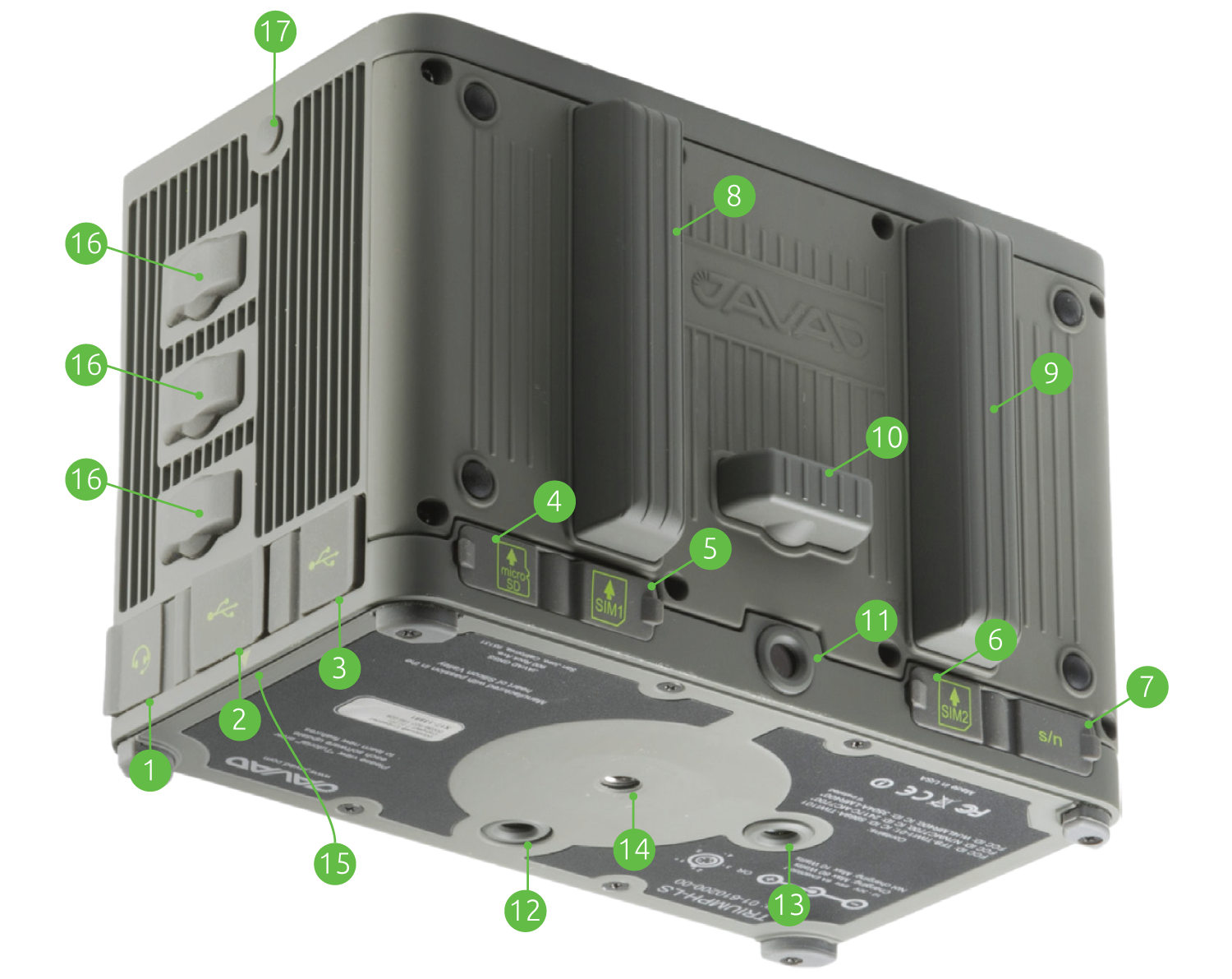
- Headset
- USB Port - Use this port for connecting USB storage drives and dongles to the TRIUMPH-LS. This is not for connecting the TRIUMPH-LS to the computer.
- Micro USB Port - This is for connecting the Triumph-ls to a computer. Use the provided cable.
- Micro SD card slot
- SIM CARD Slot 1
- SIM CARD Slot 2
- Serial number of the TRIUMPH-LS
- Internal Radio Antenna
- Internal GSM Antenna
- WiFi / Bluetooth Antenna
- Front Camera
- Bottom Camera
- Flashlight
- 1/4”x20 threads
- Slant height measurement point
- Factory port covers
- Optional shoulder strap connection plug
¶ Charging kit
Shown assembled while the TRIUMPH-LS is being
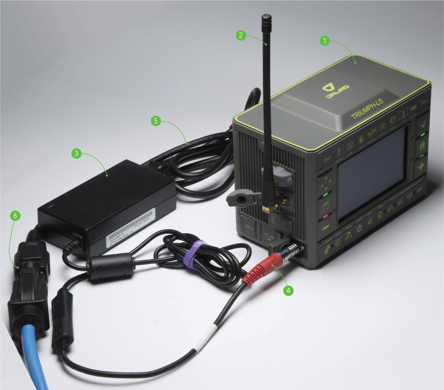
- Triumph-LS
- UHF antenna 400-470 MHz, 2.5dB, RT Angle, SMA (optional, if UHF module is installed)
- Ext Power/Charger
- Power Cable
- AC Power Cable
- AC Power Adapter
¶ Screen Anatomy - Home Screen 1
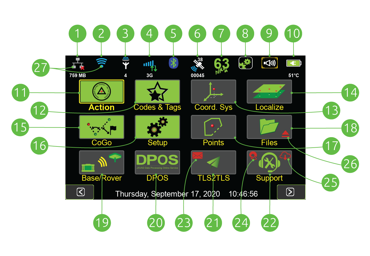
Click any icon in the top row (1-10) to open its status screen.
- LAN
- WiFi
- UHF
- GSM
- Bluetooth
- Satellites, number of tracked satellites are shown above the icon and the Receiver Name is shown below
- GNSS Interference, the numeric value is the maximum magnitude of interference among all the GNSS bands
- Setup Summary, the setup profile name is displayed below
- Volume
- Battery - The estimated hours : minutes of remaining battery life is shown below
- Action - Survey and Stake points and lines
- Codes & ShapeTags - Manage Codes and ShapeTags Coordinate Systems - lists all the system coordinate systems, not used to set the current coordinate system
- Localize - Create localized coordinate systems
- CoGo - Various CoGo Functions and Camera Tools
- Setup - Configure the setup profiles
- Points -List the project points and polylines
- Files - Browse the file system, import and export files
- Base/Rover Setup - Start a RTK base station with a UHF or SS radio
- DPOS - Data Post Processing Service
- TLS2TLS - Messaging service to exchange data between Triumph-LS units
- Support - menu, used to request support and install updates.
- New Messages Available
- RAMS Connection Established
- New Updates Available
- External Media mounted
- Inactive connections are gray and active connections are blue
¶ Screen Anatomy - Home Screen 2
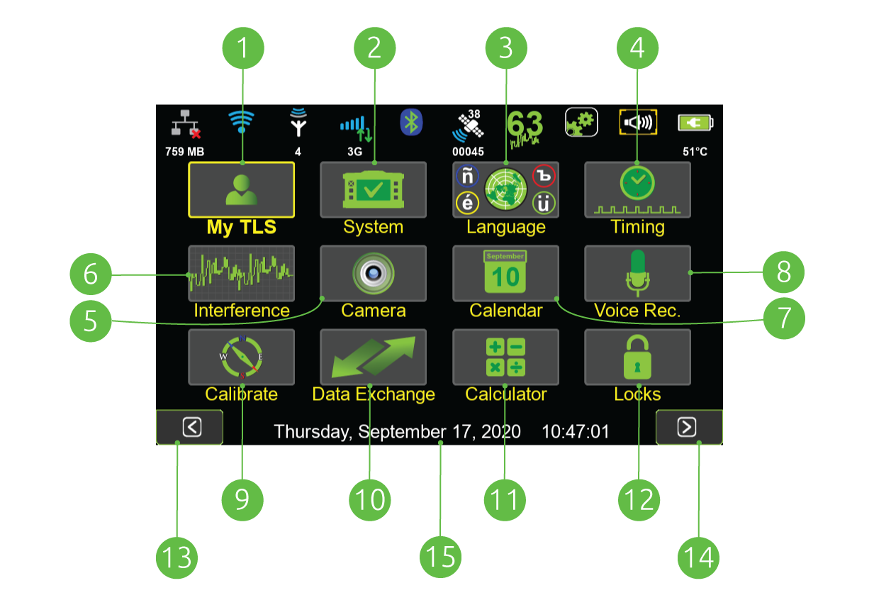
- My TLS - Unit identifications and health status
- System - Receiver details and information, etc.
- Language - Specify the language
- Timing - Configure clock display format, set alarms, schedule data collection
- Interference - Complete GNSS spectrum analyze
- Camera - Capture photos with the front and bottom cameras
- Calendar - Manage survey projects by date
- Voice Recorder - Record audio notes
- Calibrate - Calibration for the level and compass
- Data Exchange - Export / Import various data formats
- Calculator - Several different calculators are available
- Locks - Prevent inadvertent screen interactions
- Previous Screen - Advance to the Home Screen 1
- Next Screen - Advance to the Home Screen 1
- Current Time - Tap to open the Timing screen
¶ Charging the Batteries
The TRIUMPH-LS comes from the factory with the batteries charged and ready to use so you can begin exploring its interface and familiarizing yourself right away while reading this manual.
Lithium Ion batteries should not and cannot be charged when their temperature is above 40° C (104° F). They charge faster when they are cool. Therefore, it’s best that you turn off the unit when charging. Charging the unit when it’s on will cause it to charge more slowly (up to 40° C) due to its increased temperature.
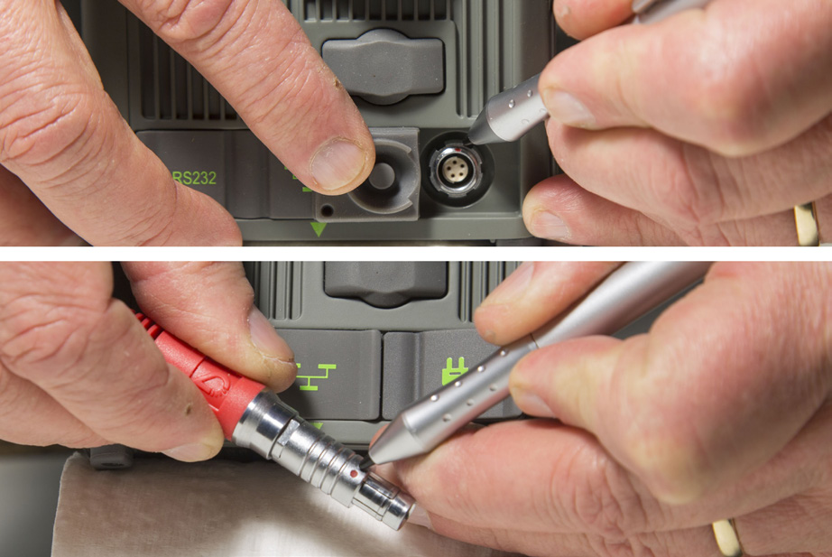
Some of the cables and their connectors used in charging the equipment may not be familiar to you. ODU style connectors are superior for a broad range of industrial power, communications and data applications that demand a precision-engineered, secure and robust solution.
When charging your receiver, be sure to line up the red dots on the connector and the charing port on the LS. Note that the four LEDs have different meanings when the LS is on from their meanings when the unit is being charged. When the unit is on, you’ll want to pay attention to the upper left LED as it alerts you of an immediate issue.
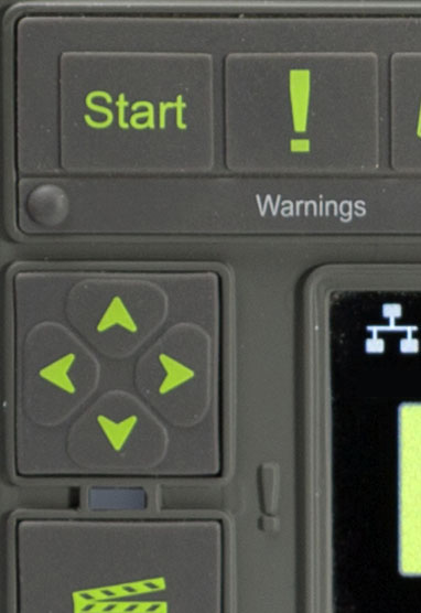 Anytime the TRIUMPH-LS displays this LED as red, press the warnings key to learn more and take any necessary corrective measures.
¶ Help & Support
J-Field contains its own ever-growing on-board manual with context sensitive help files for various screens. Press the hardware Help button to learn more about each screen. Contact information of the Live Technical Support team members are listed in Support>Live Technical Support. You are also encouraged to submit your feedback and questions to the user’s forum located at support.javad.com.
¶ Turning on The TRIUMPH-LS
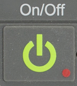 Powering the TRIUMPH-LS on is pretty straightforward with the underlying Linux operating system loading first and then J-Field subsequently booting up.
There are occasions when the system might freeze. Should you experience this, simply depress the power key and hold down until the unit powers off, about 10 seconds. Any data collected up to that point will be saved.
¶ Calibration
The TRIUMPH-LS is an advanced scientific surveying instrument. It is highly sensitive to its environment and includes a built-in magnetometer and 3-axis accelerometer.
For the visual stakeout features and the Ahead/Back and Right/Left White Boxes in the Stake Action screen to work correctly, the electronic compass readings need to be accurate. It is recommended to check the compass calibration before beginning work at a new location. To check the calibration, rotate the TRIUMPH-LS 360° and observe the compass readings in the Collect or Stake Action screen. There should be no twitching, quick jumps, or reversals of the displayed bearing or azimuth, just as a real compass would perform. If this is not the case, the compass needs to be recalibrated or it may not be in a suitable environment for its use.
Follow the instructions on the screen to calibrate the compass. When calibrating the compass, choose an area removed from overhead power lines, parked automobiles and other ferrous materials which cause magnetic disturbance. The electronic compass works in areas that are electromagnetically uniform.
The Level calibration typically only needs to be preformed once. Follow the instructions on the screen to calibrate the level.
The level sensors are sensitive to the internal temperatures of the TRIUMPH-LS. To fine tune the level calibration, a Level Offset calibration needs to be preformed. It is located in the Action Setup menu. It is necessary to reperform this calibration as the internal temperature of the TRIUMPH-LS changes.
If the Correct For Tilts option is enabled and the most accurate positions are desired, it is essential to monitor the Level Offset calibration and recalibrate when necessary.
The Camera needs to be calibrated if you intend to use the camera’s Visual Angle or Camera Offset Survey tools. This only needs to be done once.
¶ Updates

Keeping your TRIUMPH-LS up to date is nearly effortless; however, you do need to ensure that you have Internet access in order to download the firmware and software updates.
The TRIUMPH-LS will automatically detect nearby WiFi networks. To see the detected networks, as well as their respective signal strength, tap on the WiFi icon in the top row of icons on the Home screen and then at the bottom of that screen tap on Network. Select the desired access point, tap on Connect, enter the case sensitive password, if any, and the connection should be established. Once connected to a WiFi network it will be remembered and added to the Favorites and the connection to it will become automatic when it is detected.
If you do not have WiFi or for some reason are unable to connect to it, but do have a wired local area network, you can connect the TRIUMPH-LS to your network using a cable connected to the LAN port and your network interface card or router. A wireless network can also be used if you have an installed SIM card data plan with sufficient data.
Once connected to the Internet, J-Field will automaticaly check for updates. The Support button  will be displayed with the update symbol (cloud and down arrow) and a sound will be played periodically when a new update is available.
¶ Points

Tap on this icon to review points, alignments, trajectories in J-Field.
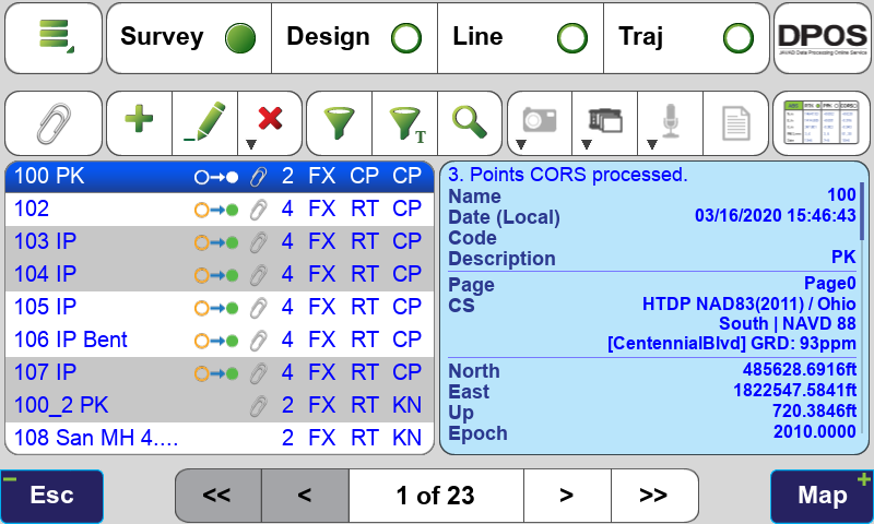
Points Screen Displaying Design Points
Each point record can have up to five types of coordinates that are displayed in the Edit Points screen:
- Design Coordinates - Imported and manually entered coordinates are populated into this field and stored in the Project’s database file with their native coordinate system as was selected when they were imported.
- Survey Coordinates - These are coordinates determined from GNSS observation. All surveyed points are stored with Survey Coordinates with WGS84 (ITRF 2008) coordinates.
- Base Station Coordinates - When a point is surveyed with RTK corrections, the base station coordinate is saved.
- Survey Shifted Coordinates - When a point’s base station coordinates have been adjusted or shifted, the shifted survey coordinates are displayed along with the unadjusted survey coordinates (Survey Origin).
- Base Station Shifted Coordinates - When a point’s base station coordinates have been adjusted or shifted, the shifted base station coordinates are displayed along with the unadjusted base station coordinates (Base Station Origin).

Edit Point Screen Displaying a Point with Each Type of Coordinate
In addition to these coordinate types, all post-processed DPOS and Real-Time Shifted coordinates are also stored in the database. These will be discussed more in the DPOS section of this manual.
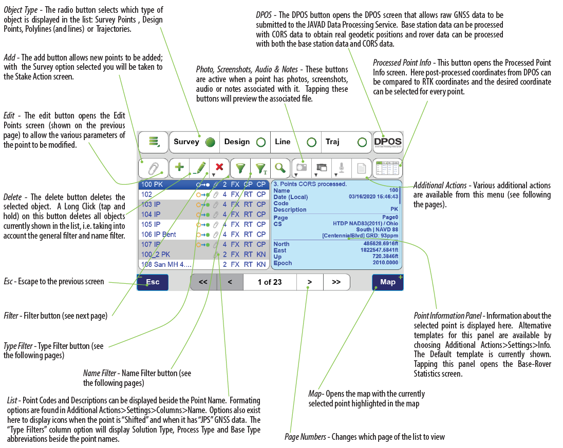
¶ Screen Anatomy - Points Screen
¶ Point Filters
Points are displayed in the coordinate system of the Current Page in the CoGo functions and in the map. All new Survey Points and points created with the CoGo functions are created in the Current Page. The Current Page can be selected by tapping  (Filter Button) to open the Filter screen. The First row displays buttons for each of the 10 pages. The Current Page is highlighted green while visible pages are shown with bold numbers and hidden pages are shown with small gray numbers. Tap a page button to toggle it between visible and hidden. Objects in hidden pages are not display in the list of objects or on the map.
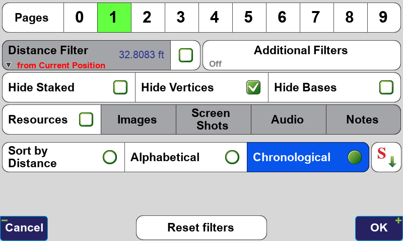
Filter Screen - Current Page is 1, Page 0 is hidden
The Pages screen can be open by tapping Pages. It displays the page names and allows it to be edited along with the coordinate system and color.
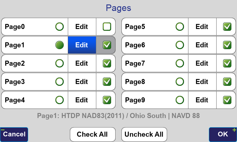
Pages Screen - Current Page is 1, Page 0 is hidden
The Current Page is set with the toggle on the left while the visibility of Pages are controlled with the check box options on the right.
The In All Projects toggle will display points from all projects. This is usually not recommended as it will slow J-Field down if many points exist.
Points can be sorted in the displayed points list by Distance, Alphabetical or Chronological. Notice the down arrow in the corner of the Distance Filter button. Holding this button down will initiate a Long Click and present additional options for the Distance Filter.
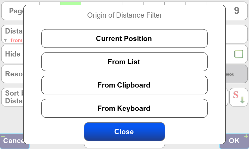
Origin of Distance Filter Options
Hide Staked hides points that have already been staked. A point is considered staked after it has been staked with a surveyed coordinate accepted for it.
Hide Vertices hides points created from imported lines from being displayed in the point’s list. J-Field defines lines as connections between points so every line must have points at its vertices. For this setting to be applied the Hide Line Vertices option must be checked in the Common Settings screen when AutoCAD, DGN or Shapefiles are imported.
The  (Type Filter) opens the Type Filters screen. It allows points to be filter by Solution Type, Processing Type and Base Type.
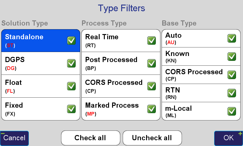
Type Filters Screen
The  (Name Filter) button enables/disables the name filter. When it is on, four additional fields are shown to the right: one text field and three switches captioned
  ,
,  and
and  . Enter the search text in the text field and specify which switches are active (activated switches have a light blue background while deactivated switches are white):
looks for names which begin from the search string;
looks for names which contain the search string in the middle, but do not begin or end with it;
looks for names which end with the search string.
Activating more than one switch combines the results: activate and searches for names which either begin with the search string or contain it in the middle.
To search for a range of numbers use the format of number1..number2. This format matches names which contain numbers in range between number1 and number2 (in the position defined by switches). E.g. if you enter 3..9 (assuming all switches are on), it will match names 3, Stake04a, Pt9, but not names 14 or Point19a.
The (Additional Actions) icon contains a list various options, settings and functions related to the Points screen. More information about the items contained in this menu can be found in each of the actions’ Help screen. Of particular interest are Settings and Cluster Average.
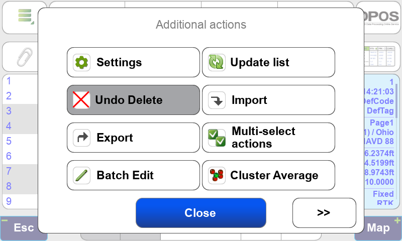
Additional Actions screen
Settings has options to allow the Point Name, Code and Description to all be displayed in the left panel of the Point screen rather than just displaying the Point Name.
Cluster Average finds groups of points in a cluster and creates an averaged point from the group.
The information panel (the right blue panel) may contain more text than fits in its view. If this is the case, tap and drag the panel to scroll its contents.
¶ Coordinate Systems
The Coordinate Systems screen allows you to quickly access and create new coordinate systems based on the predefined systems with just a tap on this icon.
It is important to note that this screen does not set the current coordinate system for the Project. To change a Project’s coordinate system choose Project>Edit Current Project>Project Coordinate System in the Stake and Collect Prepare screens. Each page in the Project can then also have separate coordinate systems, set from the Page and Coordinate System boxes in these screens.
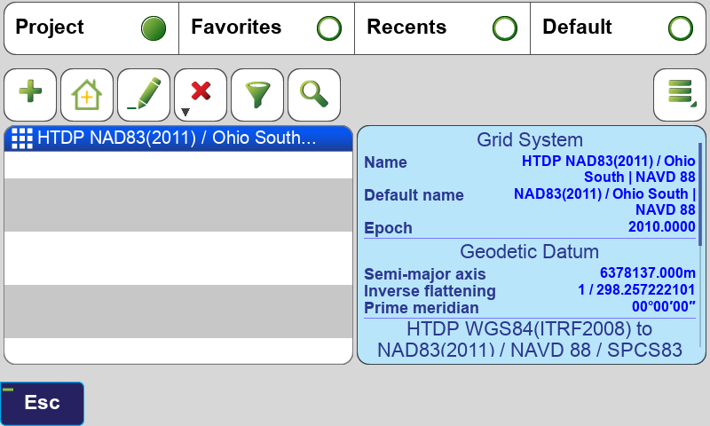
Coordinate System Screen
The tabs at the top of this screen are used to show coordinate systems that are in the current Project, in your Favorites, Recents (coordinate systems that have been used recently) and the Default coordinate systems.
To add a coordinate system to your Favorites, highlight it and then select Favorite from the menu in the Additional Actions .
.

¶ Adding a State Plane Coordinate System
To add a new coordinate system that is currently not listed in the Coordinate System screen when the All Project button is selected at the top of the screen, tap the  (Add) button to open the Coordinate System Catalog.
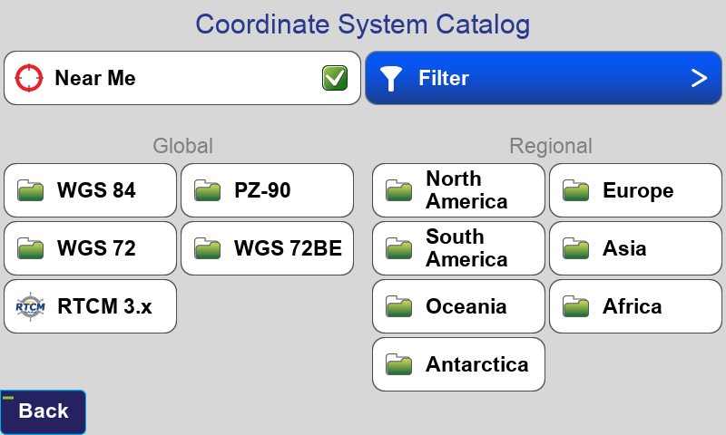
Coordinate System Catalog Screen
When selecting a Regional system for your project from the vast catalog, filter the choices to just those relative to your geographic location by checking the Near Me box. Select your Region, Country and type of coordinate system:
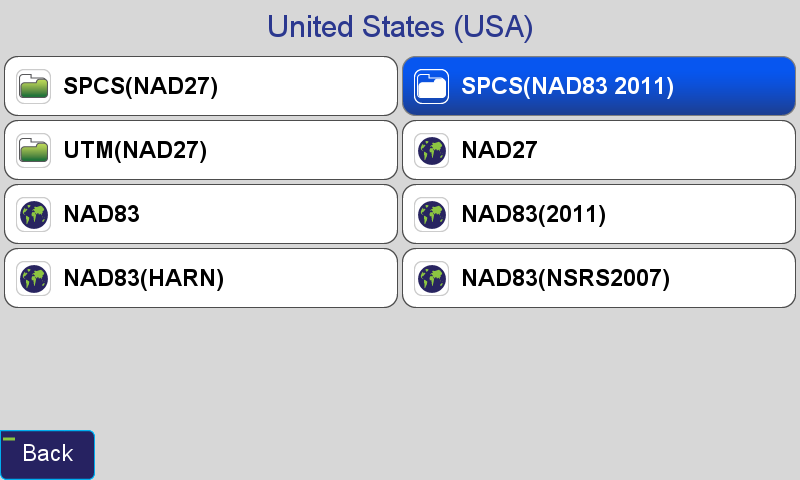
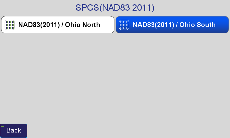
Select the appropriate Height System, Geoid, Input Epoch and Transformation. A typical coordinate system configurations for a US State Place Coordinate System is shown:
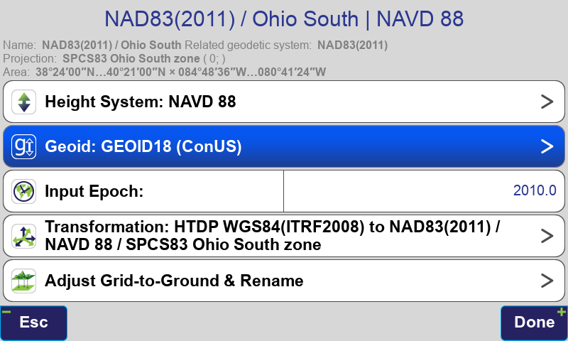
For all surveying in the US, it is strongly recommended that NAD83(2011) with Epoch 2010 be selected for all survey work as this is the current supported realization supported by NGS. The Gooid model should be “GEOID18 CONUS” and HTDP transformations should be used for compatibility with DPOS.
It is important to remember that GNSS! distances measured in State Place Coordinate Systems may not match measured ground distances exactly and typically need to be scaled to ground. For this reason you may wish to create an adjusted grid-to-ground coordinate system. Alternatively, the CoGo functions in J-Field have the ability to display and input ground distances while still working in an unmodified State Place Coordinate Systems (see the CoGo chapter of this manual for more information).
¶ Creating an Adjusted Grid-To-Ground Coordinate System
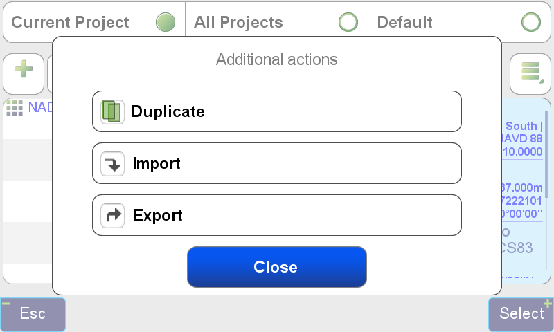
With your state plane coordinate system selected in the Coordinate System screen click the Additional Actions button and tap Duplicate to create a copy of this coordinate system. The duplicated system will be created with the date appended to the end of its name:
Now highlight the duplicated system and tap the edit icon and choose Adjust Grid-to-Ground & Rename:
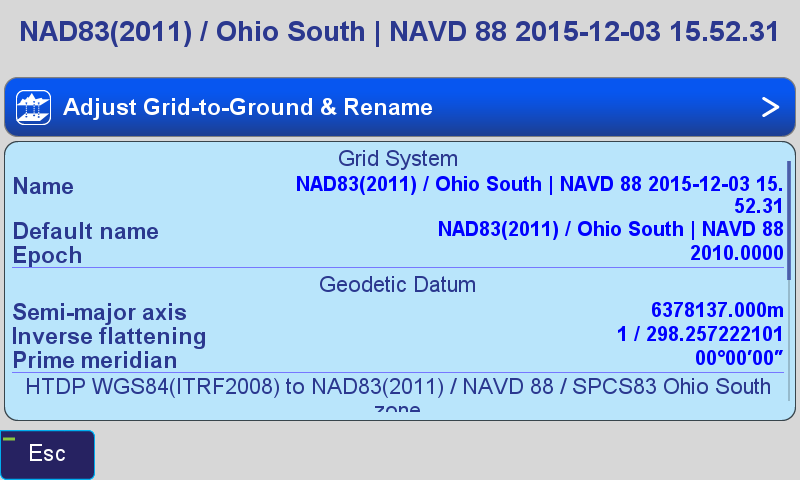
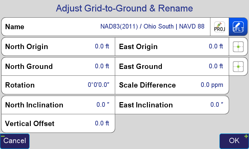
Adjust Grid-to-Ground & Rename Screen
Tap the Default  button to change the coordinate system name to the default name:
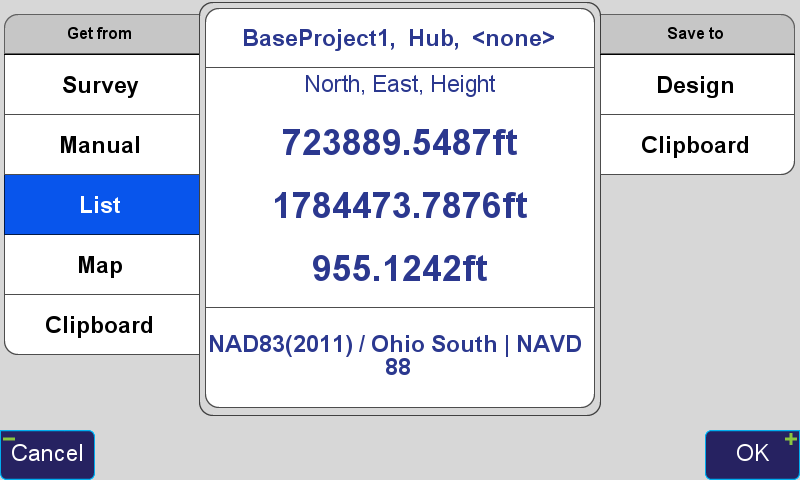
Tap the Position icon  beside East Origin to set origin point in the grid system for the transformation. Here the base station coordinate is chosen from the points List:
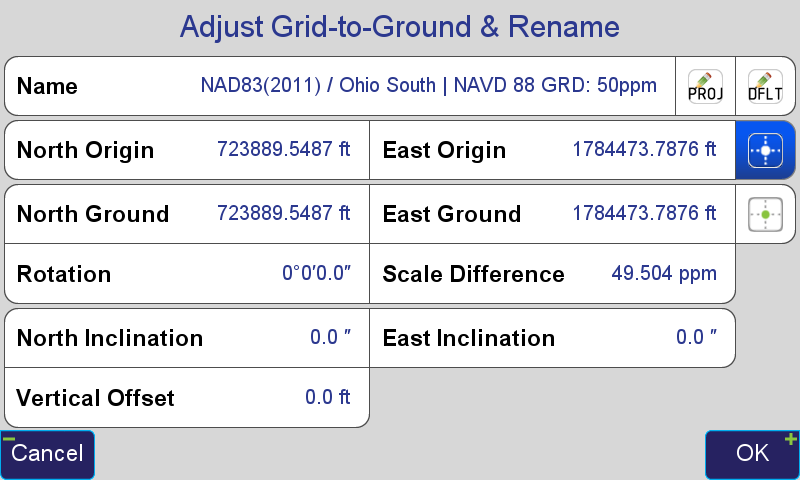
By default the ground origin point will be populated with the same coordinate and the Scale Difference is populated with the grid-to-ground scale factor calculated from that point. The scale factor rounded to the nearest part-per-million (ppm) is automatically appended to the coordinate system name:
You may also wish to round the scale difference to the nearest ppm by tapping its button and entering that value. In this screen options exist to enter a new factor as a Ratio or Ppm:
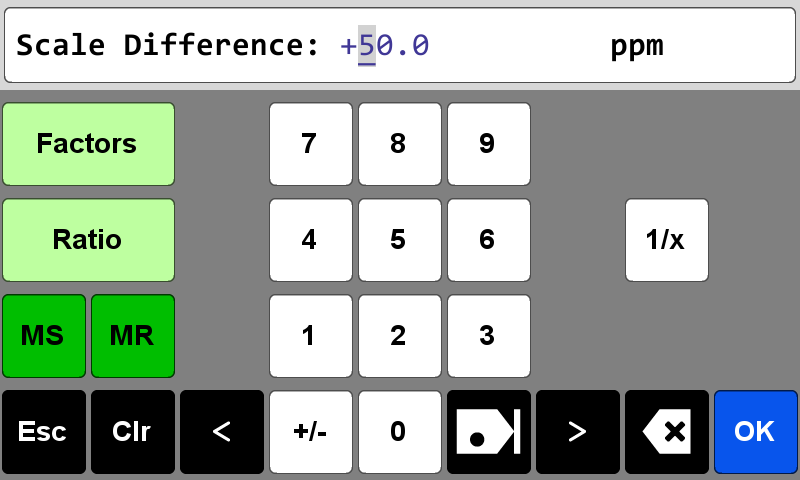
The Factors button will allow you to use the CoGo Scale Factor function to calculate a new scale factor if desired.
These settings will create an adjusted state plane coordinate system scaled around the base station and the base station coordinate will not change. This is useful for projects that have ground distances as would be measured with a total station and state plane coordinate system bearings since the rotation is set to 0. The coordinates will be very close to the real state plane system so that orthographic imagery and state plane referenced contours or elevation models can be loaded into your CAD drawings. You should be cautious when giving these coordinates to others as they may confuse them for real state plane coordinates. To solve this problem you may wish to subtract 100,000 from the North and East Ground coordinate values to create a (100,000 100,000) offset from the real state plane system. This can be done by tapping the North Ground and East Ground boxes.
Tap the button to add the current project’s name to the beginning of the coordinate system name:
Press OK and then Apply to create this coordinate system:
You can now use this coordinate system as the Project Coordinate System or just for some Pages if you choose.