¶ JAVAD MOBILE TOOLS for Android
Software manual
Version 4.5
Last Revised March 08 2022

All contents in this manual are copyrighted by JAVAD GNSS.
All rights reserved. The information contained herein may not be used, accessed, copied, stored, displayed, sold, modified, published, or distributed, or otherwise reproduced without express written consent from JAVAD GNSS.
¶ Preface
The materials available in this User Manual (the “Manual”) have been prepared by JAVAD GNSS for owners of JAVAD GNSS products. It is designed to assist owners with the operating of the JAVAD Mobile Tools Software and its use is subject to these terms and conditions (the “Terms and Conditions”).
Note: Please read these Terms and Conditions carefully.
¶ Terms and Conditions
USE - JAVAD GNSS products are designed to be used by a professional. The user is expected to have a good knowledge and understanding of the user and safety instructions before operating, inspecting or adjusting. Always wear the required protectors (safety shoes, helmet, etc.) when operating the receiver.
COPYRIGHT - All information contained in this Manual is the intellectual property of, and copyrighted material of JAVAD GNSS. All rights are reserved. You may not use, access, copy, store, display, create derivative works of, sell, modify, publish, distribute, or allow any third party access to, any graphics, content, information or data in this Manual without JAVAD GNSS’ express written consent and may only use such information for the operation of your software. The information and data in this Manual are a valuable asset of JAVAD GNSS and are developed by the expenditure of considerable work, time and money, and are the result of original selection, coordination and arrangement by JAVAD GNSS.
TRADEMARKS – Net View™, JAVAD GNSS® are trademarks or registered trademarks of JAVAD GNSS. Windows® is a registered trademark of Microsoft Corporation, Bluetooth® word mark is owned by the Bluetooth SIG, Inc. Product and company names mentioned herein may be trademarks of their respective owners.
DISCLAIMER OF WARRANTY - EXCEPT FOR ANY WARRANTIES IN THIS GUIDE OR A WARRANTY CARD ACCOMPANYING THE PRODUCT, THIS GUIDE AND SOFTWARE ARE PROVIDED “AS-IS” THERE ARE NO OTHER WARRANTIES. JAVAD GNSS DISCLAIMS ANY IMPLIED WARRANTY OF MERCHANTABILITY OR FITNESS FOR ANY PARTICULAR USE OR PURPOSE. JAVAD GNSS AND ITS DISTRIBUTORS SHALL NOT BE LIABLE FOR TECHNICAL OR EDITORIAL ERRORS OR OMISSIONS CONTAINED HEREIN; NOR FOR INCIDENTAL OR CONSEQUENTIAL DAMAGES RESULTING FROM THE FURNISHING, PERFORMANCE OR USE OF THIS MATERIAL. SUCH DISCLAIMED DAMAGES INCLUDE BUT ARE NOT LIMITED TO LOSS OF TIME, LOSS OR DESTRUCTION OF DATA, LOSS OF PROFIT, SAVINGS OR REVENUE, OR LOSS OF THE PRODUCT’S USE. IN ADDITION, JAVAD GNSS IS NOT RESPONSIBLE OR LIABLE FOR DAMAGES OR COSTS INCURRED IN CONNECTION WITH OBTAINING SUBSTITUTE PRODUCTS OR SOFTWARE, CLAIMS BY OTHERS, INCONVENIENCE, OR ANY OTHER COSTS. IN ANY EVENT, JAVAD GNSS SHALL HAVE NO LIABILITY FOR DAMAGES OR OTHERWISE TO YOU OR ANY OTHER PERSON OR ENTITY IN EXCESS OF THE PURCHASE PRICE FOR THE NETVIEW SOFTWARE.
LICENSE AGREEMENT - Use of any computer programs or software supplied by JAVAD GNSS or downloaded from a JAVAD GNSS website (the “Software”) in connection with the JAVAD GNSS receivers constitutes acceptance of these Terms and Conditions in this Manual and an agreement to abide by these Terms and Conditions. The user is granted a personal, non-exclusive, non-transferable license to use such Software under the terms stated herein and in any case only with a single computer. You may not assign or transfer the Software or this license without the express written consent of JAVAD GNSS. This license is effective until terminated. You may terminate the license at any time by destroying the Software and Manual. JAVAD GNSS may terminate the license if you fail to comply with any of the Terms or Conditions. You agree to destroy the Software and guide upon termination of your use of software. All ownership, copyright and other intellectual property rights in and to the Software belong to JAVAD GNSS. If these license terms are not acceptable, return any unused software and guide.
CONFIDENTIALITY - This Manual, its contents and the Software (collectively, the “Confidential Information”) are the confidential and proprietary information of JAVAD GNSS. You agree to treat JAVAD GNSS’ Confidential Information with a degree of care no less stringent that the degree of care you would use in safeguarding your own most valuable trade secrets. Nothing in this paragraph shall restrict you from disclosing Confidential Information to your employees as may be necessary or appropriate to operate NetView Software. Such employees must also keep the Confidentiality Information confidential. In the event you become legally compelled to disclose any of the Confidential Information, you shall give JAVAD GNSS immediate notice so that it may seek a protective order or other appropriate remedy.
WEBSITE; OTHER STATEMENTS - No statement contained at the JAVAD GNSS website (or any other website) or in any other advertisements or JAVAD GNSS literature or made by an employee or independent contractor of JAVAD GNSS modifies these Terms and Conditions (including the Software license, warranty and limitation of liability).
MISCELLANEOUS - The above Terms and Conditions may be amended, modified, superseded, or cancelled, at any time by JAVAD GNSS. The above Terms and Conditions will be governed by, and construed in accordance with, the laws of the State of California, without reference to conflict of laws.
¶ About this Manual
This Manual is designed to help you get familiar with the JAVAD Mobile Tools User Interface and introduce you to the JAVAD Mobile Tools main features.
¶ Symbols and Typographic Conventions
This Manual uses the following text conventions: Example Description.
Main Titles of dialog windows/boxes, names of menu options.
¶ Screen Captures
This Manual includes sample screen captures. Your actual screen can look slightly different from the sample screen due to the receiver you have connected, operating system used and settings you have specified. This is normal and not a cause for concern.
¶ Technical Assistance
If you have a problem and cannot find the information you need in the prJoduct documentation, contact your local dealer. Alternatively, request technical support using the JAVAD GNSS World Wide Web site at: www. javad.com.
To contact JAVAD GNSS Customer Support use the QUESTIONS button available on the www.javad.com.
¶ System Overview
Javad Mobile Tools (further JMT) is an application for Android-based smartphones and tablet devices designed to manage the JAVAD GNSS receivers’ hardware, for post-processing survey using NGS OPUS service and JAVAD DPOS. It allows configuring RTK base and rover and doing the simple RTK data collection and stakeout with coordinate system computation and organising your data. It can be connected to the JAVAD GNSS receivers via Bluetooth, Wi-Fi or connected to a network receivers. TRIUMPH-3, TRIUMPH-2 and TRIUMPH-1M are best-suited receivers for the software.
¶ Javad Mobile Tools for Authorized Receiver
Javad Mobile Tools for Authorized Receivers (further JMT-R) is a free version of Javad Mobile Tools that works ONLY with authorised receivers those have a special OAF-option. The option can be obtained from an Javad dealer or JAVAD GNSS directly. Receivers with this option have all functionality in the application. Receivers without the option can be connected to download the option from Internet or for minor functionality. All surveying functionality is available only for receivers with this OAF option. With this option there is no difference between JMT and JMT-R, That’s why we will not mention on this version further.
Note: Please keep in mind that even payable JMT requests OAF option to work with TRIUMPH-3 receiver.
¶ Installation
The JMT software can be purchased and installed from Google Play Market following the link:
https://play.google.com/store/apps/ details? id=com.javad.javadtools
The JMT-R software can be installed for free from Google Play Market following the link:
https://play.google.com/store/apps/ details? id=com.javad.javad
This manual is related to version 4.5 and previous version 3.9.x of JMT-R software in Google Play Market with following the link:
https://play.google.com/store/apps/ details? id=com.javad.javad_v3
Once purchased the software can be installed on all Android devices working with the same Google ID.
Note: 15 minutes try and money back is available for all Google Play Market applications.
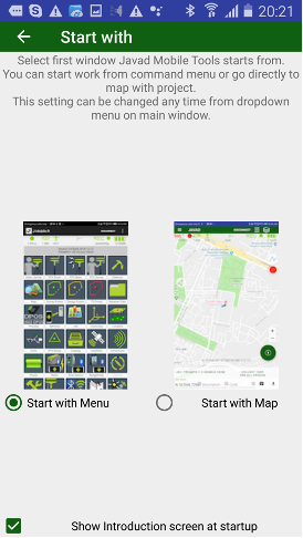
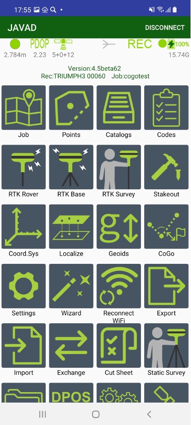
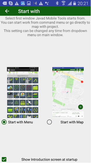
¶ Two variants of work (and Initial menu)
JMT works in variants – from start command menu or from map. With first variant after start JMT shows list of commands. With second one user directly go to map, all commands are called from left drawer menu.
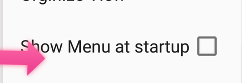
At first start up JMT asks user to use Home Menu screen at start or go to directly to working map. This setting can be changed any time with “View Menu” item in Settings screen.
 |
|  |
| 
¶ Screen anatomy
With second variant, almost all screen space is intended for user data on map or on point list.

You can see your data on map or list. To switch between map and list representation use following buttons:
 Switch to list of points
 Switch to map with points
You can control which object will be displayed on map and which background use. Select Map Provider menu item to see following dialog:
Note: Several settings depend on selected map provider.
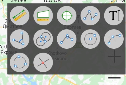
There are several controls on map. On top right the tools button is located

Then you click it, the following window with several tools appears:
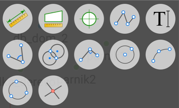
 Connect points into objects or draw on map by clicking to arbitrary places. Click on points to draw lines to the points, or click on a place on the map to draw lines to the place. Tap the button again to finish drawing.
You can set the colour for drawing and for text. Tap the button  and select the colour in the dialog.
You can modify the drawing – click to a drawing and move its vertexes. You can modify the drawing – click to a drawing and move its vertexes. Or tap the button i to get information on the object, the information dialog includes delete ability.
 Let you measure distance and azimuth. Tap the button and tap to the points or to the map to select the line or the area. Information about distance and azimuth is on top of the screen. Tap the More button near the information to open the dialog with more information.
 Let you measure perimeter and area. Tap the button and tap to the points or to the map to select area. Information about it perimeter or area is on top of the screen. Tap the More button near the information to open the dialog with more information.
 Click on a point or a position on map to see its coordinates. A design point can be created from the position.
 To add a text label on map. Tap the button then click to map. Dialog Type your message appears, there you can type a text. The height of the text label depends on current map scale. The same way you can delete text – click on it to select and tap the button
  to remove the label.
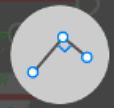
 Solve CoGo Traverse task to compute new point with given distance and direction or with given angle related to a line defined by two points.
 Solve CoGo Distance-Distance Intersection task to compute intersection with two distances to two points. Usually two points do for the task – click one to select.
 Solve Perpendicular CoGo task to compute new point with two selected points and perpendicular distance from second one.
 Draw circle by two points – Center and Radius
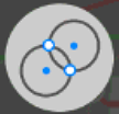
 Draw circle by three points
Draw arc by three points
 Solve CoGo Intersection task to compute new point with four points selected defining two lines, their intersection gives new point.
Other buttons on map - zoom in / out buttons and current position button – are located below them.
With this controls user can draw on map combining points into objects directly on map, compute points and compute areas and perimeters.
First click on the button opens tools box there you select tool. The button changes icon and marked with blue mark around. Then you can click to points on map. Second click to the button stops the task. Color and Delete button also appear on screen then they are required.
User can use this tools to check your data – check coordinates of any position, compute areas and perimeters.
With the connection/disconnection button on the top of the screen or just make free hand draws. Also, texts can be added, so this is useful tool for outline during survey. And in addition to drawing the tools allows do calculations to compute points by distances and angles. For example, you can draw a line and then type in its length and angle. These tools are most useful during survey to do offset surveys then GNSS receiver is connected.
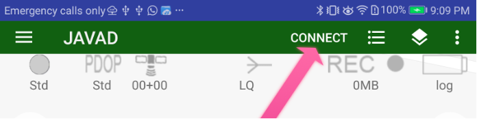
Then receiver is connected more controls appears. These controls are used for survey and stakeout.
On the top of the screen there is a status bar with information about the connected receiver. Here you can check the solution type (fixed, float, DGPS, or standalone) and accuracy, number of the satellites (GPS+GLONASS or different way depends on setting Show Satellite Type in Settings UI group), the corrections quality in percentage and the delay (with source and type), the raw file logging with receiver file name if recording, the receiver battery status, etc.

Figure 1. Status bar
On the other side of the screen other survey controls are located.

Large circle button is used to start / stop survey. It starts survey and JMT finishes surveying automatically depends on settings. User can set name, description and code for each point.
In stakeout modes user can select target and quickly navigate between targets. Pressing the circle survey button starts stakeout survey with output result report.
Long press this button shows drop-down menu to select work type.
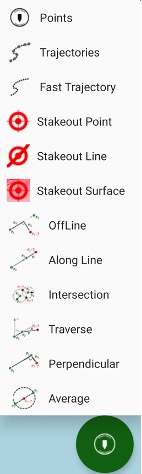
Following work types are supported:
• Points survey – survey point objects. Different type of survey settings is available – filtering by solution type, auto-completion after some time, confirmation mode, 5Hz mode. And you can use verify mode survey, Lift&Tilt survey in addition to normal point surveying.
• Trajectories survey – survey trajectory objects. Filtering by solution
type and minimal vertex distance are available.
• Fast Trajectories survey – 10Hz surveying with minimal data. The result is stored in the database at the end of the survey. (Your receiver should have options for 10Hz survey).
• Point Stakeout – stakeout point objects select from list, map or a coordinate
• Line Stakeout – stake out along/across a line defined with two points or a point with direction
• Surface Stakeout – load surface and JMT shows height difference of current height and design height
• Off Line offset survey
• Along Line offset survey
• Intersection offset survey
• Traverse offset survey
• Perpendicular offset survey
• Average two measurement (e.g. to survey tree)
Other controls allow to type name, description, codes, make photo note, audio notes for survey objects. These will be explained later in section about survey and stakeout.
Some survey controls can be added or hided using swipe up and down from text area above (or below if on top) the survey controls. Also at any time
The screen view can be reorganized using Organize View command from menu.
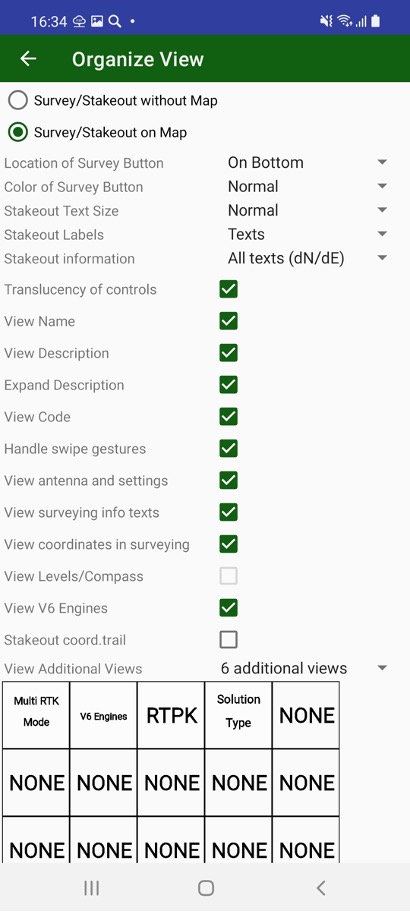
With this dialog you can
Select are you going survey on map or without map (useful for small screens)
Select location of survey control – on bottom or on top of the screen.
And select it colour.
Select best fit size for stakeout text and define do you want to use icons or text for stakeout information.
Turn on/ off translucency of controls for better visibility
Turn on / off such controls as Name, Description, Code to define your workflow.
You can turn on or off swipe gestures on map to hide / show more controls.
Show / hide Antenna and Settings buttons to free screen space
Show / hide surveying information and current coordinates to free more space on screen.
Show / hide Compass and Levels on current position.
Show / hide V6 engine control.
Show / hide stakeout coordinate trail.
Show / hide Additional information view
The additional information views can be customized – user can select information for each view. Up to 6 views can be defined. Click rectangle item on the screen and list of available items appears. Click to select required item. Click None to set empty view.
Last line of controls includes 6 configurable elements which can show additional required information. Long click on each item lets select item from dialog:
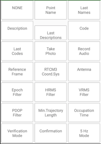
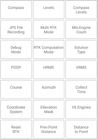

Clicking to such item also does item specific action, e.g set elevation mask, select position accuracy, activate/deactivate Multi RTK e.t.c.
This line can be turned on / off in Organize View dialog or with up / down swipes.
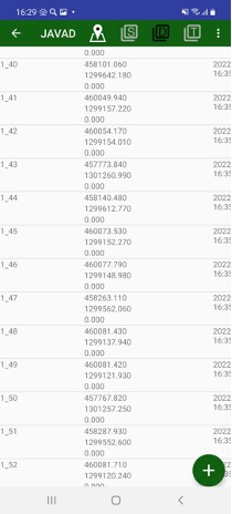
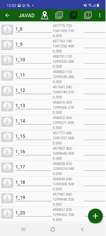
¶ Point List
Clicking  menu item, you can switch to list of points. Survey, Design, TS points or RTK Bases can be show with menu commands. Black menu item shows current selected point type.
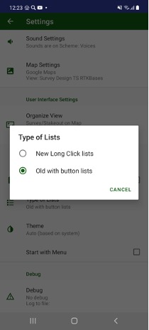
Previously list items were controlled with i-buttons on left, with new user interface you can click on an item and edit dialog will be opened and to select / handle several items can be activated with long click. Switch between the modes can be done in Settings / Type of Lists item.
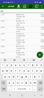
On the list, you can filter points with Search command. An edit box appears and then you type something their list will remain only points including this text in name, code, or description or coordinate.
Black menu item shows current selected point type.
On the list, you can filter points with Search command. An edit box appears and then you type something their list will remain only points including this text in name, code, or description or coordinate. List can be rearranged with Sort button. You can use different sort variants – by name, by type, by time, by code, by comment (description).

Also list can be viewed different way with View command.
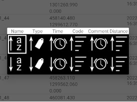
Detail list, short list, Icons and Grid views are possible to select to.
Long click on an item lets switch to multiple action mode. Check boxes appears near each item in list and action icons on top. Selected objects can be exported using Export menu item. If no items selected (no Select command performed) all points will be exported.
For Design points you can import data with Import command from menu or type them manually using + button below.
You can return back to map any time with Map menu item.
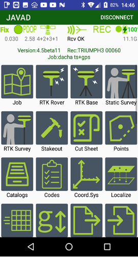
¶ Drawler menu and Main Menu
All other commands are called from drawler menu that is called from left side with either button or with left swipe. The commands are the same as in initial command menu.
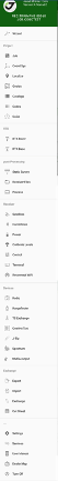
The same commands are accessible from menu screen. The screen can appear as first screen if user select this as settings.
This setting can be changed easily any time from main screen menu item.
then The JMT software user interface includes the home screen with icons.
The info button with software version and information about connected receiver and current job located below the status bar or on the top of drawler window:
 ....
.... 
The commands are the following:
• Job – shows list of jobs, let you create new jobs, modify current job, share jobs.
• Points – shows all data on the list. Different type of objects can be shown with top menu items – survey point, design points, TS points, RTK bases, Drawings on map.
• Catalog – to organize control points into the catalogs. They can be viewed with a list and on a map.
• Codes - handle list of codes. The codes can be created manually or imported from files in some formats.
• RTK Rover – starts receiver in RTK rover mode or stop RTK mode.
• RTK Base - starts receiver as RTK base. Corrections can be sent with external or internal UHF radio, internal GSM or RCV with either 3G/4G, Wi-Fi or LAN.
• RTK survey - to do a survey in RTK mode.
• RTK Stakeout – to perform stakeout in RTK mode. Point or along line stakeout mode is available.
• Coordinate System – handle list of favourite coordinate systems. There you can add / delete / edit coordinate systems and select it for the job.
• Localize – do localization of coordinate system for the job. Localization fits your points coordinates to control points coordinates.
• Geoids – shows list of existing geoids and lets surveyor download required geoids at office.
• CoGo – computation geometry routines. There you can compute design points by several tasks or compute such values like areas, distances, volume etc.
• Settings – opens all application setting dialog.
• Wizard – easy way to configure your equipment.
• Reconnect WiFi - allows you to reprogram your JAVAD receiver to be connected with the Android device by Wi-Fi. Initially you can connect to the receiver with Bluetooth and reprogram the receiver and the Android controller to be connected with Wi-Fi. External Wi-Fi access point can be used or the Android device can be set as Mobile Access Point.
Note: The receiver can be programmed for connection with an iPhone/iPad device.
• Export – outputs surveyed points, design points and drawing to different CAD/GIS file formats, including user defined text format.
• Import – inputs design points and drawing from files of different CAD/GIS formats, including user defined text format.
• Exchange – exchanges data between two controllers, the data includes points, settings, jobs etc.
• Cut/Sheet – outputs CutSheet report for stakeout.
• Static Survey - to start post-processing data collection like static, kinematic or stop-and-go work. During the data collection you can set up antenna height, site names and descriptions into the raw data file for further post-processing with Justin or Giodis software. Or using NGS DPOS and JAVAD DPOS services.
• Receiver Files - to handle the raw data receiver files. You can down- load the files to a controller or delete them to save the space in the
receiver.
• Process - to send raw JPS file to NGS OPUS or to JAVAD DPOS server to process them and get precise coordinate with even one file. JMT can receive answer automatically and store result position into the catalog.
• Services – shows settings of background services like JustinLink Exchange, OPUS Mail Reader and Mock Location (see manual further for details).
• Satellites - shows the list of satellites and sky plot.
• Correction – shows RTK corrections to check its status.
• Power – shows information about the power and charging of the GNSS receiver.
• Calibrate – lets calibrate compass and levels for Triumph-1M/Triumph-2 and levels and gyroscope for Triumph-3. For other receivers the item is blocked.
• Rangefinders – connect for data exchange with laser rangefinder with Bluetooth during offset survey. Bosch GLM100C, GLM50C, GLM120C and Leica D510. During offset survey distances measured by the rangefinders will transmit to edit boxes then device is connected.
• TS Exchange– data exchange with Total Stations with Bluetooth
• J-Tip – connect J-Tip by Bluetooth and use it to find a magnet target.
• Radio - includes the following:
• Radio Firmware Loader - updates UHF radio (external/internal) firmware.
• Repeater - configures external UHF as repeater (the radio shouldn’t
be paired to a receiver).
• Pair modem - this item is used to pair the unpaired external HPT radio equipped with Bluetooth to TRIUMPH-1/1M or TRIUMPH-2. If the radio has already been paired, use Pair HPT radio application to unpair and repair the radio with USB.
Note: Alternatively, you can use the NetView&Modem desktop application for the device pairing.
• Terminal - allows sending low-level GREIS commands to JAVAD
equipment;
• Controls - shows list of low-level actions for your receiver like Clean NVRAM, Reset receiver, Update receiver firmware, Update receiver OAF, Save/Restore receiver settings into a file.
• NMEA Output – enables NMEA messages to output to selected port.
• Quatro / Duo – for SIGMA receivers with such board, the item let you setup Sigma and Duo parameters and monitor angles computed by the board.
• Spectrum – shows spectrum of GNSS in the current location. That lets you estimate quality and problems while surveying.
• User Manual – loads and shows User Manual for the software.
• Dealer Map – list of JAVAD dealers in selected area.
• Exit – different options to exit the application.
¶ Data organization
¶ Data location and Android 10
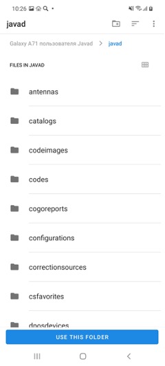
JMT stores all data inside javad subfolder in shared folder of internal storage. The folder path is specific for each device, for Victor-2 controller the path is /storage/emulated/0/javad. E.g. path to jobs folder is /storage/emulated/0/javad/jobs.
Android 10 and above is required applications to store data in scoped internal storage. The two advanced is pointed by Google – no application can access data to other applications and no unused data remains after an application deinstallation. All apps since November 2021 should conform to the rules, so JMT 4.5 lets customer stores all data inside scoped storage. Unfortunately no other application (including file browsers) can access the data, only JMT sharing abilities can be used to access your data.
That’s why JMT allows two abilities:
– Continue store your data in shared (external for the app) storage. In that case JMT uses special techniques to access the data, that decrease performance of the application. But all the data will be visible and accessible.
- Use recommended by Google internal scoped storage and limit access to your data
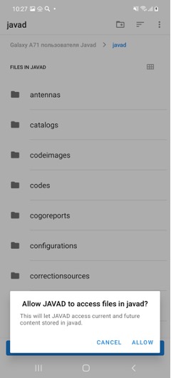
So after update of JMT you have to reset access to your previous data. And at the first run, Javad Mobile Tools asks access to previous data with following dialog:
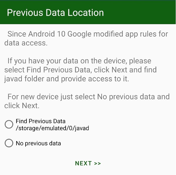
If you have used JMT and have data, please select first check mark – Find Previous Data. Then after Next select javad folder, previously used, click Use This Folder button and click Allow to allow JAVAD JMT full access to the folder back.
If you just installed JMT and don’t have a previous data yet, please select No previous data and go Next.
Then you should decide there your data will be located. As it has written before, there are two possibilities:
- JMT data can be located in scoped internal storage of JMT. No other application can get access to the files, including File Browser or other sharing software. Only JMT access to the data. Deinstallation of JMT stops access to the data at all and can delete your data at all.
- JMT data can be located in shared storage and JMT performance will be reduced.
To let’s select the data location the following dialog appears:
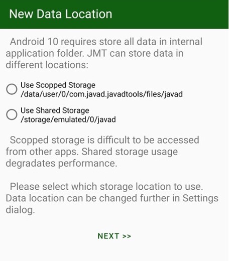
Select radio button and click Next. If you have previous data, JMT moved them into the new location.
The dialogs appears only at initial start after installation of the app or update from previous version.
You can change data location and copying your data using Settings / Data Location folder item at any time. Please keep note, that the settings is dangerous because it affect all your data. Please backup you data for any case before moving them into a new location.
¶ Jobs
At start-up Select Job dialog is shown:

Figure 4. Select job
The last opened job can be selected or tap Select other job..., to select the job from the list. The job is a set of data related to one project. It is a folder with data stored inside javad/jobs sub-folder on your controller. The database with all survey info is located there. All raw jps files and all other files are stored in this folder.
You can move or backup all data related to the job just by moving or copying the job folder. The needed coordinate system for a job can be selected here.
Every job includes all surveyed points and trajectories, all drawn lines. Also it includes all design points to be staked out. Total station points, stations, and measurements also are stored in the job file.
The control points are job independent and are organized in catalogs. Each catalog has its own coordinate system and all points in the catalog are in the same coordinate system. The only one opened catalog is accessible from other screens.
To manage the job, select Jobs item in the Home screen and the list of jobs
appears. Use the filter to search the job: order jobs by name, date, size and coordinate system. Also you can see the stored jobs on the map and on the calendar.
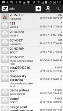
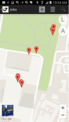
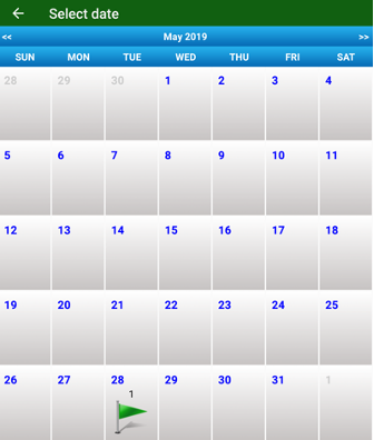
Figure 5. List of jobs, the jobs on the map and on the calendar
Deleted job(s) will be moved to the javad/trash sub-folder from original javad/jobs folder.
¶ Points
The same way as the jobs the points can be managed. In addition, type of objects is switchable with icons on top of the list - Tap the Survey Points, Design Points, TS points or RTKBases item to see the list of points.
S icon – for survey, D – for design, T – for TS points, R – RTK Bases.

Figure 6. Point type icons
Points can be sorted by name, time, code etc. and searched using a filter.
You can create new design points or edit the existing.
For survey points you can edit the name, comment and code, or change antenna type and height (which causes coordinate recompilation).
Also you can export all types of points to custom format text file and import design and TS points from the custom format text files or from some GIS/CAD files.
¶ Catalogs
Catalogs are set of points. As many as need catalogs can be created. Each catalog has its own coordinate system. Catalogs are job independent. You can select points from current catalog to make localization, to start RTK base etc. They were designed for control points but can be used for you usefull way you want to. The same sort and search options are available for catalogs as for jobs and points. Select Catalog to see the control points in the list or on the map. Here the control points can be created, edited or deleted. In addition, you can create a new catalog or switch to another catalog, and delete an old catalog as well.
Only one opened catalog is accessible from other screens. Then you open a catalog, previous open catalog is closing.
While creating a new catalog the coordinate system can be set. All points in one catalog are always in the same coordinate system.

In catalog you see you points in plain text delimited by commas in following format:
Name, North, East, Up, Code, Description
So you can just type in your points or copy / paste from other documents. The data can be imported and exported with standard format JMT knows.
¶ Receiver connection types and reprogramming
There are several ways to connect your Android device with your GNSS
receiver. It can be:
• Bluetooth connection
• Wi-Fi connection. The Android device is the Mobile Hot Spot for the receiver connection
• Wi-Fi connection. The Android device and the receiver are connected to the same Wi-Fi Access Point (to a mobile Wi-Fi router or an office Wi-Fi access point)
• Internet connection to the remote receiver (connected to Internet directly or via NetHub).
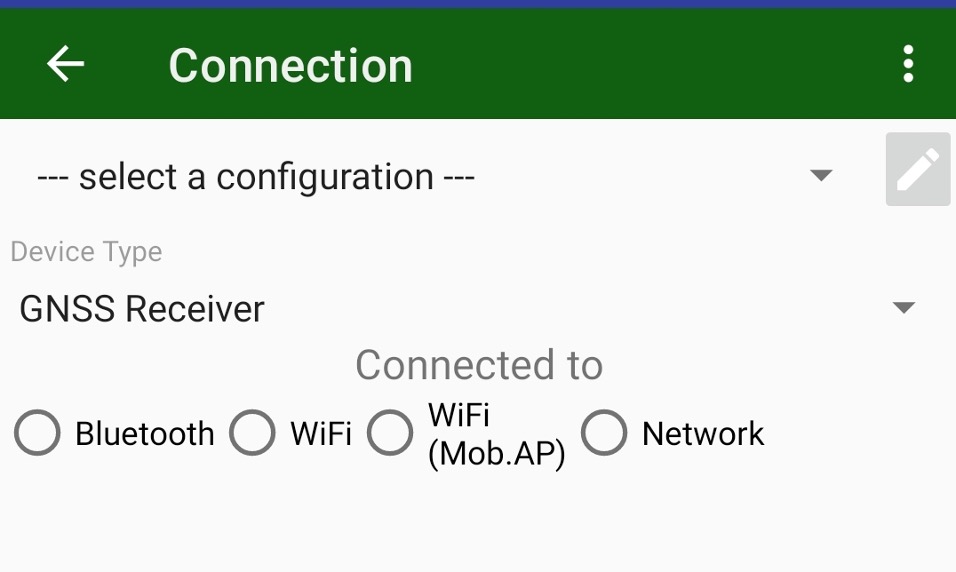
Previous connection configurations can be selected with Select Configuration drop-down menu. For initial or a new connection please select radio button to select connection. After connection established it will be added into the connection configuration list for next time.
¶ Bluetooth connection
The Bluetooth connection is the easiest way of the connection. Activate the Bluetooth radio button in the Connected to field.
You don’t need to configure anything, just select the receiver in the blue list of Bluetooth devices available in the range and set the pairing PIN code for the first time only (1234 by default). Next time select the connection from list of connections and JMT starts the connection to the receiver.
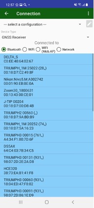
Figure 7. Bluetooth connection
¶ Wi-Fi connection
The Wi-Fi connection is much faster than Bluetooth and slightly longer in the range. But Wi-Fi connection requests the receiver configuration.
The receiver should be preconfigured with NetView software or connected initially via Bluetooth (see above) and configured using current settings of the Android device. Select Reconnect Wi-Fi item from the home screen. You should enter the Wi-Fi password because the connection is secured.
There are 3 ways for Wi-Fi reprogramming:
• connection to the Android as Mobile Hot Spot;
• connection with the Android to the same Access Point;
• programming for iPhone/iPad connection.
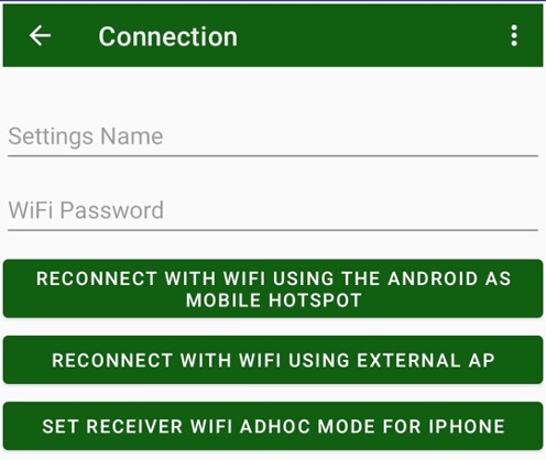
In the dialog enter the Wi-Fi password and the settings name. Select the action by tapping the appropriate button.
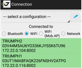
After the reprogramming, JMT switches to Wi-Fi connection mode and starts to search the JAVAD receivers available in the Wi-Fi network. All found devices will be shown in the green list. After connection is established, the IP will be stored and the next time you just need to select the connection from list of connections.
¶ Connection to the remote receiver
The last variant is the connection to a remote receiver. Select the Network
radio button in the connection types.
Type the receiver IP address and port with login and password. After connection is established, all connection details will be stored and the next time you can select the connection from the list of connections.
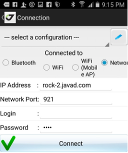
Figure 10. Connection to the remote receiver
¶ Connection through NetHub
If your receiver doesn’t have a public static IP to connect to, you can use the NetHub software on a computer with public static IP to connect two receivers and even a receiver and a controller. To perform this, configure your receiver to enter the Internet and connect to the NetHub software. Using NetHub configure the receiver to be accessible remotely. So, you can connect it using JMT. In JMT select Network as connection type, enter an IP-address and a port of the NetHub service and type in the login “nethub:” prefix and receiver name, you set in NetHub. For example, nethub:TR_103, where TR_103 is the name of your receiver in NetHub. Click Connect button. After the connection is established, all connection details will be stored and the next time you can select the connection from the list of connections.
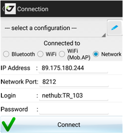
Figure 11. Connection to the remote receiver
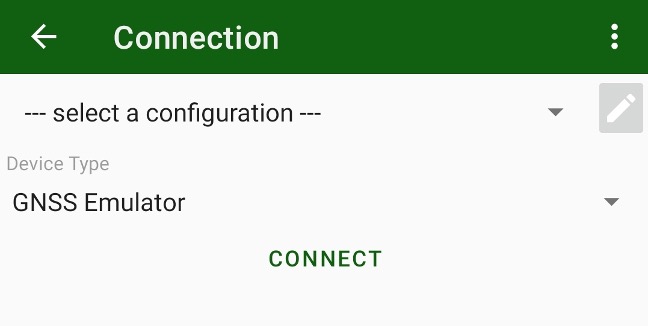
¶ Connection with emulator
JMT let’s you use a GNSS emulator to learn JMT and demonstrate its features. In connection select GNSS Emulator
¶ Edit connection configuration list
The edit list of existing connection configurations (e.g. to remove obsolete connections or rename them) click edit button with pencil icon.
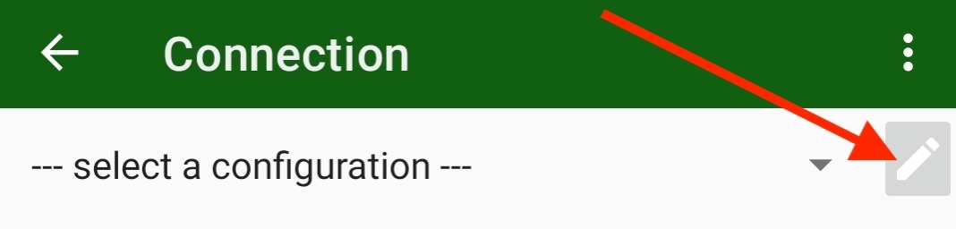
The following dialog appears:
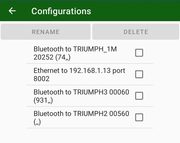
There you can select items and delete or rename them.
¶ Information on receiver
¶ Status bar
During the survey on the top of the screen the status bar is shown. Their icons and values are:
• precision of current solution;
• current PDOP
• current number of GPS + GLONASS satellites
• REC flashing when raw data logging is on with file name
• receiver battery status and receiver raw data free memory size
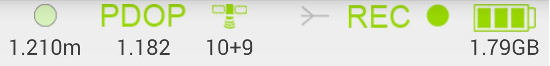
Figure 13. Status bar
By tapping different the icons, you can temporary switch to information screens and returns back to surveying screen.
• Satellites – to satellite table view and sky plot;
• Power – to power settings screen;
• Recording – to file manager screen.
By tapping to the satellite numbers on the status bar you can switch to the Satellites list and sky plot.
¶ Skyplot
Each concentric circle represents the elevation angle above the horizon. The outermost circle corresponds to 0 degrees above the horizon. The center of the sky plot represents 90 degrees above the horizon. The satellite markers for different systems are shown by the different colours. The degree of filling of marker reflects the value of the signal-to-noise ratio.
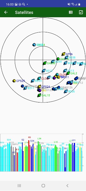
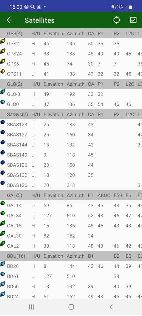
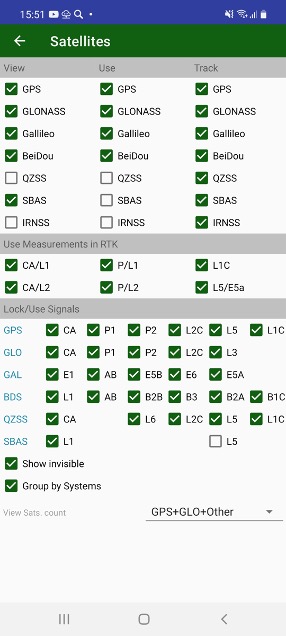
Figure 14. Sky plot and satellites table
The screens can be configured with Sats menu item. Satellite Constellation screen appears there you can turn on and off GLONASS, GALILEO, Beudeo, QZSS, SBAS satellites. They can be turned off only for showing on the screen, used for RTK solution or don’t be tracked at all. Other group lets control using individual measurements in RTK. And the final group of controls lets track and use separate signals.
Show invisible checkbox allows to show invisible (untracked) satellites in skyplot and table.
View Sat. count drop box let’s select how to display number of satellite on status bar.
¶ Corrections
By tapping the Correction icon on status bar the Correction screen appears. In the screen, you can see the status of radios, corrections, etc. Items depend on correction sources. In any way, they include radio link quality in percent and correction delay in seconds. Number of correction and number of broken (bad) corrections. Information on RTK base currently using and distance to it.
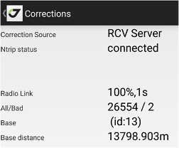
Figure 15. Corrections
¶ Power status
By tapping the Power icon on status bar the Power screen appears. In the screen, you can see the status of receiver’s power supply. If the receiver supports the power status displaying, you can control the battery status/ charging, enable the output power to serial ports, and enable the low power mode. Also, you can enter receiver to Sleep Mode or switch it off.
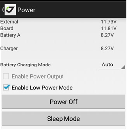
Figure 16. Power
Note: You can power off the receiver while exiting from JMT using Exit item from Home screen.
¶ Post-processing surveying
You can set the name for new receiver raw file. Antenna height and type, description and audio notes or photos can be attached to the file. Set occupation time and logging rate, and start the static survey by tapping Static button. For static survey you should tap antenna button before every surveying to avoid the surveying with wrong antenna height used in the previous survey session.
JMT programs your receiver to close the static survey automatically so you don’t need to monitor the surveying all the time. Although you can see the surveying status at any time or stop it and close static file then you need this.
On the bottom of the screen you can see logging history graph. It shows data recorded to raw file for every satellite as green horizontal bars. White gaps between them indicated on satellite tracking lost. The graph outputs maximum uninterruptable time for 6 and 10 satellites and whole number of measurements in the raw file. The information lets you monitor quality of the post-processing data and estimate probability of good processing in post-processing for the file. For static survey minimal interval in the graph is 30 seconds, for Stop-Go survey 5 seconds. For Stop-Go survey the graph shows yellow and red vertical lines indicating Start and Stop events.
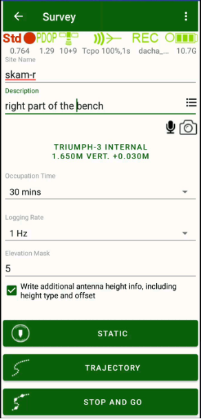
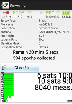
Figure 12. Post processing surveying
The same you can do for Trajectory surveying by tapping the Trajectory button. During trajectory surveying you can set the event marks inside the raw file using Event button.
With JMT you can perform the Stop and Go survey. You can survey several sites into one receiver file. The length of full survey should be at least half hour but each point can be limited to one or two minutes of collection.
Tap Stop and Go button and on the next screen you can control the surveying process.
You can start the site surveying with Point button and finish it by tapping the Point button once again. Antenna height, point name and description and photos and audio notes can be attached to each point. All the information are stored inside the raw file (for audio and photos only reference names are stored inside the file).
You can start trajectory surveying by tapping Trajectory button as well. Also, you can finish one type of surveying and start another just tapping other button, in other words, you can start trajectory surveying after point surveying just by tapping the Trajectory button without tapping Point button. When the stop-and-go survey is done, stop it and close receiver file using Close File button.
¶ Receiver file management
After surveying you can handle the receiver files by selecting the File Manager item. There you can see the list of the files. You can sort and search them the same way as in other lists (jobs, points, catalogs etc.).
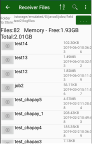
Figure 17. File list
By tapping on the icon near to the file name you will see the menu-list of actions for the receiver file. Select to delete or download the file.
You can restore deleting on receiver files. Select menu item Deleting Mode. In the mode you can see deleted files in the list of files. Then you click to a file item, Restore command will be available. To switch back to normal mode you can use menu item again, it changed to Normal Mode.
¶ OPUS and DPOS processing
After the file(s) has been downloaded to the controller you can process jps files to compute coordinates using NGS OPUS (works only in USA) or JAVAD DPOS (works in USA and where DPOS servers are installed).
Select Process command on the drawler menu or home screen and the list of downloaded files appears. The files can be arranged the same ways as described above for other lists: they can be sorted using the list, map and calendar.
To operate with a file, tap an icon near it. The list of commands What to do with the file appears.
You can delete the file or process it with OPUS or with DPOS.
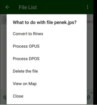
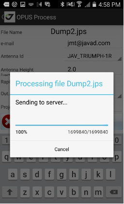
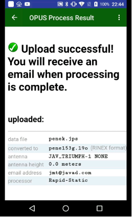
Figure 19. What to do with the file
Tap Process OPUS. The JMT software tries to read the antenna model and its height from the file and convert the parameters to the vertical height.
Note: OPUS doesn’t support the slant heights.
Enter the antenna height manually if needed.
Select Rapid Static (less than 2 hours) or full Static (greater than 2 hours).
Set Project Id to use the file in OPUS Project processing. Enter an e-mail address to receive the results from OPUS.
If you enter jmt@javad.com, JMT will receive automatically the answer and deliver it to your Android device when ready.
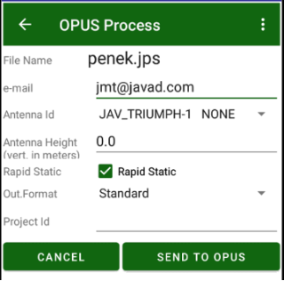
Figure 20. OPUS process
Tap Send to OPUS and the progress dialog appears. Then upload is over, report window appears. You can close it, if you set jmt@javad.com. After some minutes JMT reads the answer and shows the result. The result can be stored as text file. Select the check mark Save Report to save.
Additionally, JMT can extract the coordinates from the file and add them to the catalog with WGS84 coordinate system, if Add to Catalog is tapped.
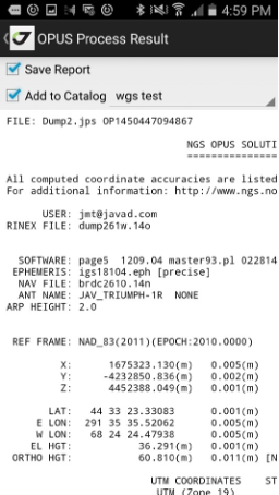
Figure 22. OPUS processing result
The same steps as described above for OPUS, can be performed for JAVAD DPOS processing. But with DPOS you can more options. User can select Network to process. JMT analyses the file to find nearest network and you can select other
The result will be ready immediately after the processing. You can save the result to the file or add the result coordinates to the catalog.
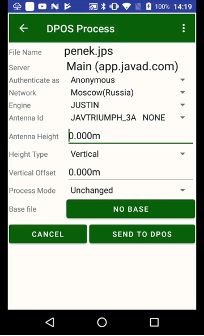
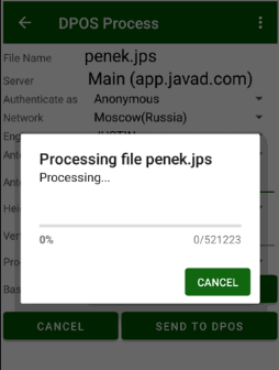
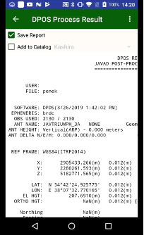
Figure 23. DPOS processing
For JAVAD DPOS you can select antenna height type (slant or vertical) and type vertical offset. Also, you can set which server will be used for processing. DPOS allows setting up your own DPOS servers.
Note: For details contact JAVAD GNSS DPOS Team.
The report can be seen at any time by tapping the file and selecting View OPUS or View DPOS item from command menu.
¶ VB-RTK
Then your RTK Base recorded raw file and your rover stores rover positions from this base, after process on OPUS/DPOS you can adjust (shift) the RTK Base position and correct all the rover points.
That’s why you don’t have to setup RTK Base to precise geodetic coordinates – the correct rover coordinates will be computed by DPOS/OPUS coordinates. This work mode is called VB-RTK.
Then you process your base file in the report you will see VB-RTK button. Pressing on it show list of rover points with their current and new coordinates. You can adjust them pressing Do VB-RTK button.
¶ Hybrid RTK
Then you work in a canopy place or with large interference place and can’t get good fix solution for a long time, Hybrid RTK mode saves you. Hybrid RTK mode is activated in survey settings. Just set period of time that you expect to have robust post-processing file.

Then Hybrid RTK is activated for each survey point a corresponding raw file started to collect. (JAVAD GNSS receivers can collect two files, that’s why this will not harm your main raw file.) The file name includes your job name and the point name.
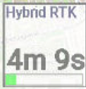
You can control status of Hybrid RTK in Additional View Hybrid RTK item – in Orginize View dialog set check box View Additional Views and select Hybrid RTK with long click to some item. The item shows either remain time or ready status.
 -----
----- 
Then you get good fix solution, the file will be just removed after the point survey stop. Then you can’t collect good fix solution for the time you set for Hybrid RTK, JMT save the point with temporary coordinates and store the raw file.
And then you surveyed all points, you can go to Receiver Files and select Download Hybrid-RTK files menu item. JMT downloads all Hybrid-RTK files for the job. At the end of work, stopping RTK Base, JMT suggests you download raw file from RTK Base and the suggest to process it with DPOS/OPUS.
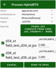
Then you process your files you can compute their position from CORS stations only or you can obtain precise position of the base file with CORS and then computes rover files from this base. This mode is more useful because base station has long observation length and can be robust computed from distant CORS stations. And Hybrid RTK rover files are very close to the base file that’s why they can be computed even with such observation time.
For such mode press RTK Base button in DPOS dialog and select base file. Set its coordinate as computed with CORS.
Then DPOS/OPUS report is ready you will see list of points with computed correct coordinates.
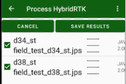
Press Save Results to set coordinates for the points.
¶ RTK works
The JMT software allows operating JAVAD GNSS receivers in RTK mode. It is possible to configure the receiver as an RTK Base or as an RTK rover for RTK Survey or RTK Stakeout. Some steps should be performed before starting. You need to create a job and set the coordinate system with height system and localization, then configure your receivers as an RTK Base and an RTK rover with required correction source.
Bellow you will find the detailed description.
¶ How to create a Job
To create a new job, use Job item on the home screen. Tap the + button. New job screen appears.
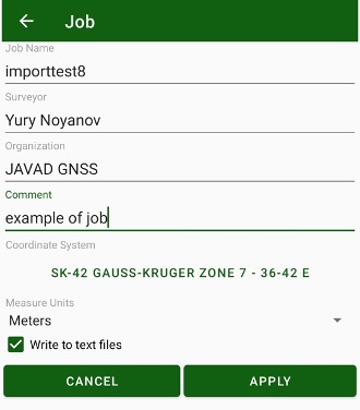
Figure 24. New Job
Enter the job name and information about the job:
• surveyor and organization names;
• arbitrary comment;
• coordinate system for the job
• measure units for displaying.
Activate Write to text files check mark to save the information to the text files in addition to the job database.
Note: This feature can be useful, but it makes the work slightly slower. It is possible to activate or disable the mark at any time further. Additionally, you can modify the job name and surveyor / organization names later with Edit command.
¶ Coordinate systems, units and localization
Set the coordinate system for the job. Tap the button with coordinate system name and you will switch to Coordinate system favorites dialog. It shows your frequently used coordinate system. Select the coordinate system from the favorites list.
All favorites coordinate systems are stored in javad/csfavorites sub-folder. Some their binary files are stored in javad/geodata folder. JMT tries download missed binary files then a coordinate system has selected. Please provide Internet access to your mobile device then you add new coordinate system or import jobs with new coordinate systems. Otherwise you can put the binaries manually to javad/geodata folder
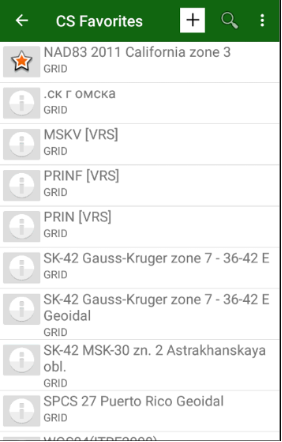
Figure 25. Coordinate System favorites
To define a new coordinate system tap + button on the top. The list of available coordinate system types will appear.

Figure 26. Coordinate system
It provides several possibilities:
• selecting a predefined coordinate system from the database;
• adding a local system (and later make the localization after surveying
several points);
• adding the user defined system typing all parameters (ellipsoid, datum,
projection).
• reading coordinate system from receiver that was connected to VRS with RTCM3 messages with CS info.
• import CS from file
¶ Predefined coordinate system
Select the World or Continents items to select the coordinate system from the world or from the country specific group.
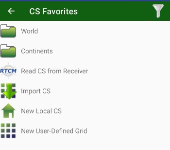
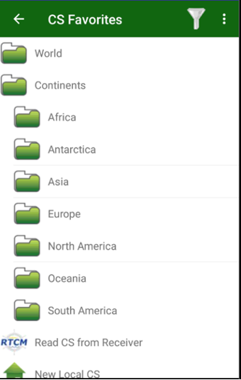
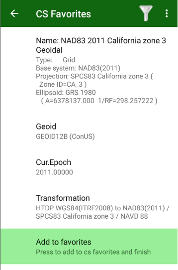
Figure 27. Predefined coordinate system
Go through the tree of grouped coordinate systems and find the required one and tap it.
A new screen with parameters of the coordinate system appears.
Enter the name for the selected system, select the height type or geoid type (or remain the ellipsoidal height) and select the appropriate transformation if several transformations are available.
You can set coordinate system Epoch. This parameter is useful for USA NAD83 transformations. Finally tap Add CS to favorites button to add the coordinate system to the favorites list.
If name of the coordinate system is already in the list, the system will be replaced without a warning. And every job stores their own copy of the coordinate system. Then you open a job its coordinate system will replace coordinate system in csfavorites folder and in the list.
Tap Geoid to set the height system and tap Transformation to select the transformation.
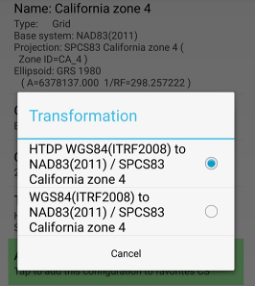
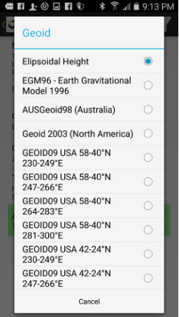
Figure 29. Transformation and geoid selection
¶ Local coordinate system
To enter a new local coordinate system, use New Local CS item.
Enter the name of the coordinate system and tap Add CS to favorites to finish.

Figure 31. New local coordinate system
The localization procedure for the coordinate system can be done later from the Job dialog.
¶ User defined grid system
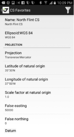
Figure 32. User defined grid system
Select New User-Defined Grid and enter the grid parameters.
Enter the following parameters for the system:
• name for the coordinate system;
• ellipsoid;
• projection type;
• projection parameters (the parameters depend on projection type);
• 7 datum parameters (3 offsets, 3 rotation and scale) - you can type it
manually or select from the list of existing datums;
• datum direction (WGS84 to the CS or from this CS to WGS84);
• select geoid (or remain ellipsoidal);
Tap Add CS to favorites button to add the coordinate system to the favorites list.
¶ Coordinate system from VRS
Nowadays there exist VRS networks that transmit coordinate system parameters to best fit to land coordinate systems in different places. JAVAD receivers can read such information and JMT can create a coordinate system from such information. To read coordinate system from such VRS, connect receiver to the VRS and wait till the correction pass to the receiver. Then you can go to Coordinate Systems dialog and tap + icon to add a new coordinate system. Select Read CS from Receiver item. The screen with parameters of the system appears. There you can set a name for the system and store it in the list of favorites coordinate system.
Note: The receiver store information about last coordinate system from VRS till restart.
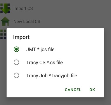
¶ Import of Coordinate Systems
Coordinate system can be imported from files of previous Javad field software – Tracy and from .jcs files created with J-Field or Justin. Press + button and select Import CS item. The following screen appears to select file with coordinate system.
¶ Localization
Sometimes you may need to match the coordinate system with your coordinates. This can be performed with the localization. The localization allows calculating the local transformation parameters between two co- ordinate systems, defined by the sets of points with coordinates known in these systems.
Define the set of points in your coordinates and in coordinates in the known coordinate system.
You can use surveyed coordinates and design coordinates from the catalog. The JMT software computes transformations using 4 horizontals and 3 vertical parameters:
• rotation, scale, offset north, offset east;
• delta height, north inclination, east inclination;
• (if surveyed points are used latitude0 and longitude0 as parameters for oblique stereographic projection parameters).
To start localization process select Localize item from Home screen.
You can type the parameters manually, but alternatively, you can use the identical points. Identical points dialog shows the list of pairs of designed and surveyed points. To add a new pair tap + button on the top of the list.
To select or modify the surveyed or designed point, tap the button in the identical point line. To delete an identical point, tap the red check mark on the left.
The identical point can be used for plane and height parameter computation or for plane parameters only computation or for height parameters only. You can check this using drop-down menu near each identical point.
Also, you can see the residuals for each identical point. The large residuals in localization means an error.
After you apply the parameters, the JMT software modifies the coordinate system script in the job with the localization. You can perform the localization several times to make it more precision with adding the additional identical points.
Note: The localization item is unavailable when you are creating a new job. Selected Edit Job command, to perform the localization and you won’t be able to modify the job coordinate system.
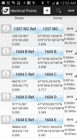
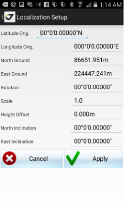
Figure 33. Identical points
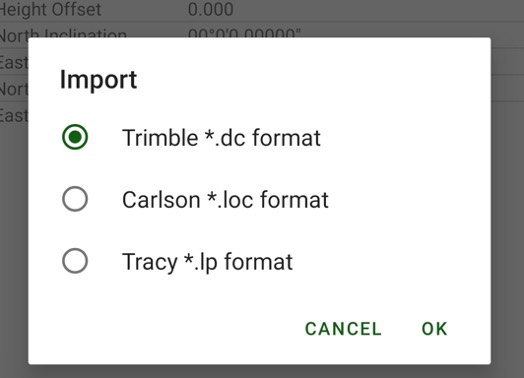
Also, the user can import localization from a Trimble .dc file, Carlson .loc file or Tracy.lp file. To do this select Settings | Import. Select format.
Then select localization file from the file tree. The location data appears in the screen.
¶ Geoids
The JMT software uses the plane and height coordinate system simultaneously. Define the height type and geoid when you are preparing the coordinate system for the favourites list.
If you are selecting the geodetic or grid system, the geoid selection is available. Define the user-defined grid system.
The geoid binary files can be downloaded from the GeoData server automatically. The binary files for computations should be stored to javad/ geodata folder (not to csfavorites subfolder ).
Note: If JMT doesn’t load it automatically you should place the files manually to javad/geodata folder.
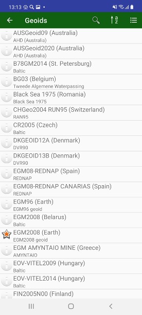
The list of geoids can be shows in Geoids screen. There you can download required geoids in office and create coordinate systems with the geoids, before go to field.
¶ Correction sources
For RTK works you may need to setup your equipment to transmit RTK correction from RTK Base receiver to RTK Rover. You can pre-configure your base and rover receivers once and don’t reset them each survey session. The internal receiver firmware will configure everything after receiver is turned on.
To configure RTK Base, you need to set the base coordinates or average them and after the surveying process them using DPOS/OPUS VBRTK procedure.
You can easily set up your Base and Rover using the JMT software. There are several correction sources are supported with JMT:
• External radio connected via Bluetooth or internal TRIUMPH-1/M radio
• UHF radio
• FH radio
• GSM direct call aka CSD (with internal TRIUMPH-1/M GSM radio)
• Internet corrections (with Mobile 3G HotSpot or internal Triumph-1/M
3G radio)
• VRS network with Ntrip or RCV protocol
• RTK Base station with static IP
• NetHub
It is convenient to create the separate correction source items for different works and select when needed quickly from the list, without retyping all parameters every session.
To create a new correction style, select new FH radio, new UHF radio, new NTRIP server, new RCV server, new RCV Base item. List of available items depends on currently connected receiver abilities (e.g. GSM items are available only the Triumph-1 with internal GSM is connected to). New correction style screen appears, set the settings for the radio, enter the correction style name to store the configuration in the list of correction sources.
To modify the corrections source settings, tap the button near the description.
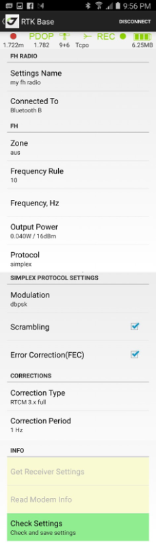
¶ FH Radio
You can set the Rover radio connected to Bluetooth B (for external Bluetooth radio), Serial B (for external radio connected with cable to port B of TRIUMPH-1/M), or Internal radio (for internal radio of TRIUMPH- 1/M).
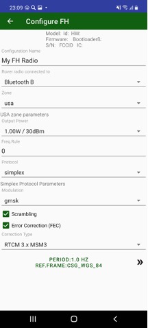

Figure 34. FH radio configuration on the rover side
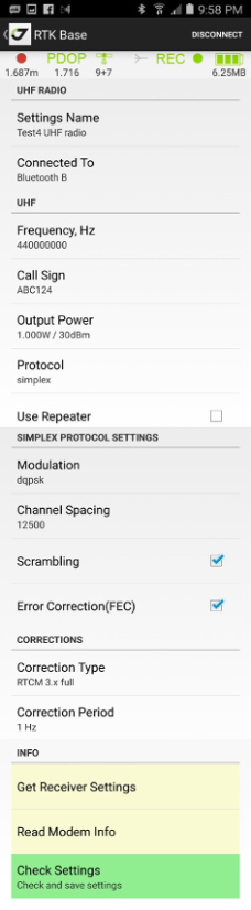
¶ UHF Radio
You can set the Rover radio connected to Bluetooth B (for external Bluetooth radio), Serial B (for external radio connected with cable to port B of TRIUMPH-1/M), or Internal radio (for internal radio of TRIUMPH- 1/M).
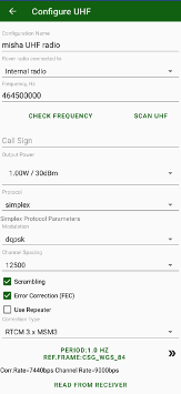
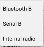
Figure 35. UHF radio configuration on the rover side
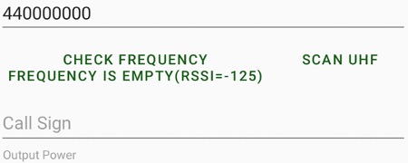
¶ UHF Scan and Check frequency
Selected UHF frequency can be checked is it free or other UHF radio works on the frequency. Just click Check Frequency to let UHF radio check scan the frequency and is it empty.
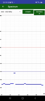
Also JMT can run range scan for selected frequency range. You can see signals in the range and check which frequencies are empty.
¶ NTRIP server
For the NTRIP rover corrections connect to the network (NetHub, VRS, FKP etc.) using standard NTRIP protocol. The rover will receive the correction via Internet.
There are several ways to connect the rover to the Internet:
• the connection is established by Android device using built-in 3G Internet, JMT runs NTRIP client and reads the correction and passes the corrections to the rover;
• the receiver is connected to 3G Wi-Fi Mobile HotSpot and internal firmware of the receiver runs NTRIP client and reads the correction;
• the receiver uses internal 3G/GPRS radio to connect to the Internet and the internal receiver firmware runs NTRIP client and reads the corrections.
Note: To check the Internet connection you can use, tap Internet from drop-down list.
Source Table button downloads the NTRIP source table and displays the screen to select a mountpoint. All other items are depended on the selected mountpoint.
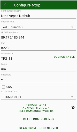

Figure 36. NTRIP connection configuration
Pressing >> button opens advanced settings. There you can set period of corrections from the base, set auxiliary port (then corrections go through controller) and set reference frame and RTCM3 coordinate system correction infos.
Note: An auxiliary port is required for JAVAD receivers to work then corrections and commands go through the same port. This port should be enabled by OAF options for input corrections of selected type (RTCM3, CMR etc). By default, this is port dev/ser/b for Triumph-1 receiver. Contact with your dealer for this setting. If the corrections are from built-in receiver 3G, WiFi or LAN the settings is not required.
Reference Frame is used then RTK base is set not in WGS84 but in NAD83 (this is common practice to USA).
RTCM3 coordinate system correction controls are requires then RTN transmit location dependent corrections including offsets in coordinate systems depends on rover position. To support such technique user can set Use CS from RTCM3 check mark and set which corrections he want to use (usually all).
¶ RCV server
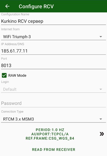
Figure 37. RCV server configuration
There are several ways to connect the rover to the Internet:
• the connection is established by Android device using built-in 3G Internet, JMT runs NTRIP client and reads the correction and passes the corrections to the rover;
• the receiver is connected to 3G Wi-Fi Mobile HotSpot and internal firmware of the receiver runs NTRIP client and reads the correction;
• the receiver uses internal 3G/GPRS radio to connect to the Internet and the internal receiver firmware runs NTRIP client and reads the corrections.
For RCV rover corrections go either from a network without a protocol or
from a standalone RTK base receiver with static IP.
RCV can operate in two modes: TCP data flow without authorization (so called TCPO) or with a login/password authorization (TCP). Number of connections to one TCPO port is unlimited. 5 different TCPO ports can be configured for different types of corrections on one base receiver.
One TCP port allows only one connection with login/password. Base receiver allows up to 5 TCP ports (from TCP A to TCP E).
Note: NetHub software allows more complex configuration. See NetHub user manual for details.
Note: To check the Internet connection you can use, tap Internet from drop-down list.
Note: An auxiliary port is required for JAVAD receivers to work then corrections and commands go through the same port. This port should be enabled by OAF options for input corrections of selected type (RTCM3, CMR etc). By default this is port dev/ser/b for Triumph-1 receiver. Contact with your dealer for this setting. If the corrections are from built-in receiver 3G, WiFi or LAN the settings is not required.
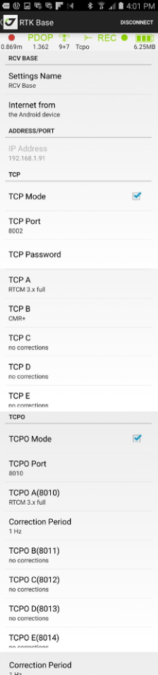
¶ RCV Base
If your RTK base station has a static IP you can configure it with RCV Base screen. You can configure the receiver as Internet accessible RTK base station with Internet access with this Android device or with internal receiver firmware using Wi-Fi or internal 3G/GPRS.
Note: In any case the Android device SIM card, 3G Wi-Fi router SIM card or internal 3G/ GPRS radio SIM card should have permanent static IP accessible from Internet for other rover receivers.
In that case, you can set TCP (with authorization) and TCPO (without authorization) ports in the base receiver.
¶ RTK Base start
To start receiver as RTK Base tap RTK Base item on the home screen. RTK Base screen appears. Enter several settings to start RTK Base:
• station name and id
• base position and reference frame
• antenna type, antenna height
• correction source
• raw file logging
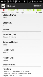
Figure 38. RTK Base Configuration
You don’t need to reset all base station parameters every time, you can just modify the antenna height and position. When you come to a new base position, enter the new antenna and new position (either from catalog or manually) and tap Set Coordinates button. Base station will be ready immediately.
Then you set your base position it
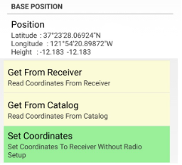
Figure 39. Base position
For full base station reset use Start station button on the bottom.
The raw file logging you can control with following items in the screen:
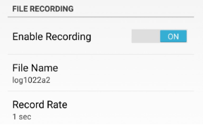
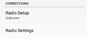
Figure 40. File recording and Corrections screens
You can create a new correction source settings by selecting new FH radio, new UHF radio or new RCV Base item in Corrections list. New correction style screen appears, set the settings for the radio, select the correction style name to store the configuration in the list of correction sources. To modify the corrections source settings, tap the button near the description.
Below are the examples of the different type settings for RTK base.
FH Radio ---- UHF Radio ------ RCV Base
¶ RTK rover setup
To configure the RTK rover, select RTK Rover. Here you need to select the correction source, check/modify correction source parameters. By tapping Start button configure your receiver as RTK rover.
No need to reset the rover every time before survey. Once configured, the internal firmware sets all parameters when receiver is powered on.
If you want to set the different source type or other parameters, or for the first time, you need to configure your receiver as rover.
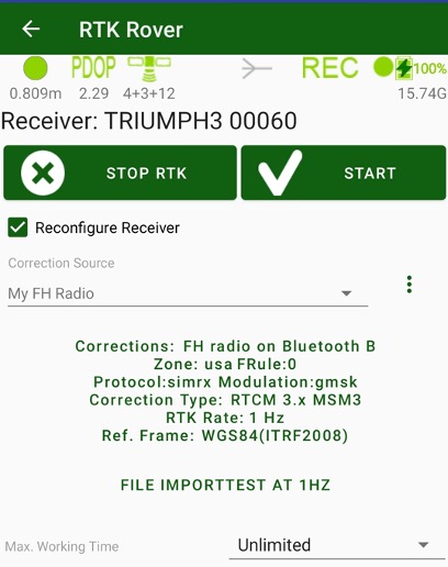
Figure 42. RTK Rover screen
Disable Reconfigure Receiver check mark, to don’t modify current receiver parameters. Otherwise, enable the check mark and select correction source you want to apply to.
You can create a new correction source by selecting New xxxx item. Dialog to create new correction source appears then you selected such item. There you can set name for the correction source and all its parameters.
Below the selected correction source name correction source settings button is located. There information on the selected correction source are displayed. Click to the button to see/modify parameters of the correction source with special dialog depends on source type.
And below this button is located button to configure 3G, WiFi or LAN depends on Internet From setting in the selected correction source. Then Internet from Android is selected, no such settings and no this button.
Next item shows name of current raw logging file. Click on it to set name for the raw file that will started then RTK will started. There are several settings in the dialog will be opened:

Receiver File Logging check mark controls will receiver log file started and stopped then RTK Rover will started or stopped.
Logging Rate sets rate for messages in this file.
Store Base Corrections enables to record correction data from RTK Base into the same file. So result file can be processed with Justin without second base file.
Max.Working Time lets limit working of your receiver as rover and stops radios after given time. That is useful then you use payable services like Ntrip. Select Unlimited if you don’t need any time limitation.
There is the status bar on the top of this screen. This status bar in the RTK
mode is slightly different from post-processing mode.
It shows:

Figure 43. Status bar
There is the status bar on the top of this screen. This status bar in the RTK
mode is slightly different from post-processing mode.
It shows:
• Solution type (green means Fixed, orange - Float, red - standalone and yellow - DGPS) with precision (HRMS) value text. Grey colour means that you required coordinates in local coordinate system instead of WGS84 and your VRS doesn’t transmit such data., please go to correction source and set WGS84 instead of RTCM3 in Reference Frame.
• PDOP;
• Number of satellites GPS+GLONASS+(GALILEO/BEIDOU/SBAS);
• Corrections. The waves go outside for base and enter inside for rover, text label explains correction source and quality and delay of the corrections;
• Raw data recording status. It is green or red then it is not enough memory in receiver for raw files. It flashes then file logging is on and current log file name shows in the text label;
• Receiver battery status. It is yellow or red then receiver battery should be charged. Label below shows free memory of receiver memory for raw file logging.
To control the raw file logging, you can use the File logging button, that shows information on current receiver file logging. Pressing the button opens File Logging dialog with following settings:
• Receiver File Logging check mark enable or disable writing the raw file at RTK rover start. Then writing to receiver file is enabled you can set next parameters:
• File name;
• Logging rate (depends on your receiver OAF abilities up to 100Hz);
• Elevation mask;
• Store base correction check mark enables write base corrections into the rover file. In that case, to process, you don’t need the second file from the base. The feature mostly used for debugging and analysis;
• Write additional antenna height info, including height type and offset control how JMT writes free-form events to the raw file. Without the mark, JMT converts all antenna height to vertical height without offsets then writes event into raw file. Such events can be correctly read by any post-processing software including text and other. When the check mark is activated JMT writes antenna height events in the more complex way, including height type mark (s or v) and offset. So, in Javad post-processing software like Justin and Giodis you can read and see the information about antenna height as you typed it.
The last line defines in which coordinate system RTK base station works. You can select WGS84(ITRF2008) or another NAD83 system. The last item in the control (RTCM3) allows configuring the receiver to use the RTCM3 coordinate system corrections. If the user selects the RTCM3 item, the coordinate system for conversions back to WGS84 should be selected. Or Read from receiver item can be set in coordinate system then create correction source. In that case after receiving corrections JMT will wait till coordinate system data came to the receiver and then creates coordinate system for RTCM3 conversions.
Tapping Read CS from Receiver you can read and set current coordinate system from the receiver manually. Coordinate system data already have to came to receiver from RTCM3 corrections.
Note: Then RTCM3 reference frame is selected receiver doesn’t produce coordinates till coordinate system data came from corrections. If your RTN doesn’t send such data you will see grey circle in solution type and don’t have coordinates at all. Please contact with your RTN owner before activating RTCM3 reference frame.
After start RTK you can do RTK tasks as RTK Survey and Stakeout. Use items on Home screen to start the activity.
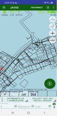
¶ Map and RTK works
By default JMT opens map screen to see all information together (survey points, design points, RTK bases) on the map. Then initial menu is selected you can use Map command from the menu screen. On the Map you can do several actions:
• Combine points into an object by drawing lines between them.
• Modify drawn lines;
• Draw text notes on the map;
• Modify text notes;
• Measure area and perimeter of drawn objects or by selecting points;
• Do a CoGo computations
• Select point or points by clicking on it.
• Delete selected points.
• Survey points on map.
• Survey trajectories on map.
• Stakeout points
• Stakeout along line
• Stakeout on a surface
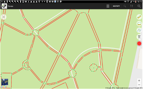
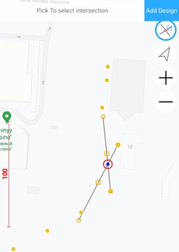
Figure 61. Map
To start actions on map like drawing or measurements click top right button and available tools appear in the box:
Click on it and the button will be highlighted with blue border and icon that means the tool is active.
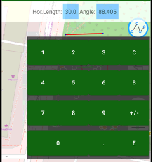
To combine points into an object, tap button  and then click on points to draw lines to the points, or click on a place on the map to draw lines to the place. Tap the button again to finish drawing. Clicking to
  button let you undo last drawing action. Clicking color circle button, let you select color for the drawing polyline. On the top of screen you can see information line with distance and angle fields. You can click to the fields to type data manually with on screen keyboard, press E button to finish typing.
This way you can compute a new point with given direction and distance from another point (direct cogo task). Then you drew two points you can compute a new point with given angle from these two points (traverse cogo task).
To add a text label on map, tap the button  , then click to map. Dialog Type your message appears, there you can type a text. The height of the text label depends on current map scale.
You can set the color for drawing and for text. Tap the button and select the color in the dialog.
You can modify the drawing – click to a drawing and move its vertexes. Or tap the button  to delete the drawing.
The same way you can delete text – click on it to select and tap the button
to remove the label.
Tapping the button  you can move the map to the current position. The button is available then the receiver is connected to.
Last two buttons  and
and  let you measure perimeter and azimuth. Tap the button and tap to the points or to the map to select the line or the area. Information about it perimeter or area is on top of the screen.
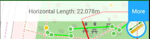
Tap the More button near the information to open the dialog with more information.
You can copy the information by clicking blue buttons near each value. To select which information to show on the map, use Map Points command to see the following dialog:
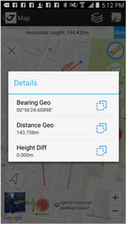
Figure 62. Map Points
Tap  button let you see coordinate a position. Click a position on map or point and label with coordinates appears.
Also coordinates appear on top of screen in the information bar. Add design button there let you add new design point for stakeout.
There are several CoGo buttons –
Traverse task
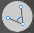 Traverse task there you select two position on map or points and type traverse length and angle with on screen keyboard. Then you can click Add Design button to create new design point.
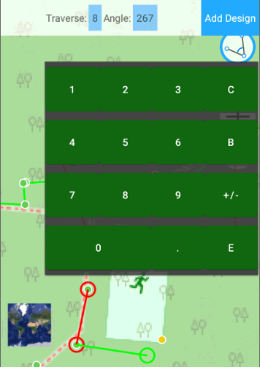
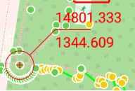
Selected two points are drawn in red and computed point is shown in green.
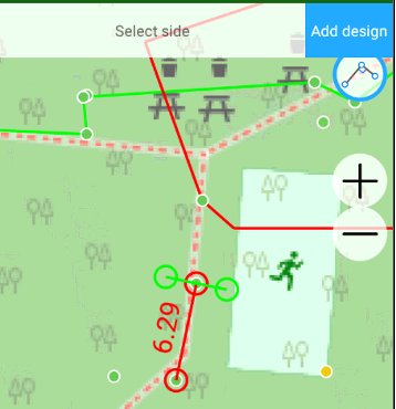
Distance-Distance intersection task.
There you select two position on map or points and type two distances to new point with on screen keyboard. Two possible points are result of the task. The points are shown with green circles. Click to one of the circle to select
Then you can click Add Design button to create new design point.
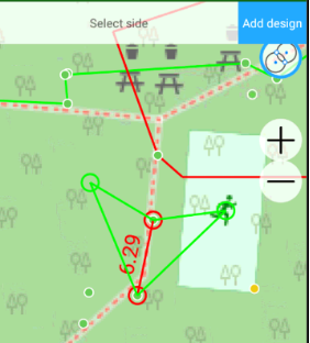
Offset task.
You select two position on map or points and type two distances to new point with on screen keyboard. First distance is along the line and second is across the line. Two possible points are result of the task (Left or Right). The points are shown with green circles. Click to one of the circle to select required.
Then you can click Add Design button to create new design point.
Intersection task.

You select two drawn lines on map, intersection point are shown with blue circles. Click to it and red circle marks selected point. It can be added into design points.
Then you can click Add Design button to create new design point.
All drawing information are stored in the job and can be exported to CAD formats.
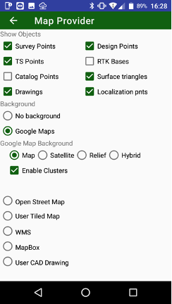
User can use different map backgrounds and show different items on the map. To setup select Map Provider item in menu.
Map Provider dialog appears. There you can set following settings:
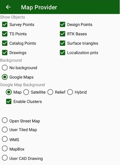
Show objects to show
- Survey Points
- Design Points
- TS Points
- RTK Bases
- Catalog points
- Drawings
- Catalog points
- Localization points
- Surface triangles
Select background:
• No background map
• Google Maps;
• Open Street Maps;
• MapBox map
• User defined tiled map in .maptiles format or .sqlitedb3;
• User CAD drawing in DXF/DWG file.
For user raster format you can use the different application like MapTiler (https://www.maptiler.com/) that saves data to .mbtiles format. Or you can use JAVAD JustinLink application that saves to raster format .sqlitedb.
You can put the result raster file to javad/osmmap of your Android device to see it as a background map if User Tiled Map is selected.
For vector files, you can select User CAD Drawing and select a .DWG file. JMT will use it as a background map.
¶ Working on Map
Very useful is surveying/stakeout on map. In the mode, you can see your position among surveyed points and map background. That lets you verify the position and check correctness.
You can do different types of work – survey points, survey trajectories, stakeout points, stakeout along line, stakeout on surface. To select work type long click big circular button and following drop-down menu appears:
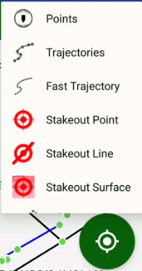
To start survey press the action button. Survey progress you can see on the top of the screen. Also audio alarms inform you on epochs and result.
Note: you can configure surveying sounds with Sound button in RTK Settings screen.
Before surveying you can set name of the point and type a description for it.
You can combine surveyed points into objects using button. You can change colour for the drawing lines with button colour circle. The colour of the button shows current drawn colour. Then you click to a drawing line, a grip marks appear on each vertex and side. You can mode sides and vertex using the grips. Then a drawing is selected you can delete it using button with cross mark.
¶ RTK Survey
After connection to receiver, the there are several controls for RTK Survey.
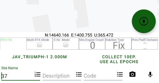
The main surveying buttons are on the top of the control. Big circle button starts and stops the survey. You can do difference type of surveys. Long click this button shows menu to select survey type with the drop-down menu.
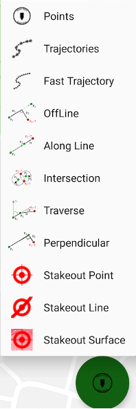
Figure 45. Select survey type menu in RTK Survey screen
The following survey variants allow:
• Points survey – survey point objects. Different type of survey settings is available – filtering by solution type, auto-completion after some time, confirmation mode, 5Hz mode. And you can use verify mode sur- vey, Lift&Tilt survey in addition to normal point surveying.
• Trajectories survey – survey trajectory objects. Filtering by solution
type and minimal vertex distance are available.
• Fast Trajectories survey – 10Hz surveying with minimal data. The result is stored in the database at the end of the survey. (Your receiver should have options for 10Hz survey).
• Off Line offset survey
• Along Line offset survey
• Intersection offset survey
• Traverse offset survey
• Perpendicular offset survey
Then survey selection type is set the button changes icon. Pressing it once you can start surveying. Pressing it again you can stop surveying and store result object. Then Occupation time is set JMT automatically presses the button again and finishes the survey after required number of collected epochs. And you can finish the survey manually anytime before this by pressing the left button before auto-complete.
Then “Confirm Point” option is set,

Confirmation dialog appears.
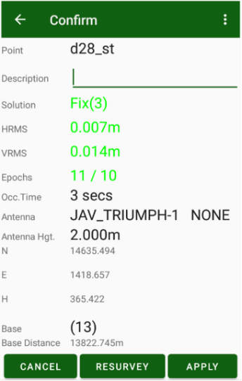
Figure 46. Confirmation screen
You can check the result solution type and coordinates and modify point description. If the result is ok, tap Apply to store the point. Or tap Resurvey to repeat surveying of the point.
The Site name and the Description items are for the new point/trajectory to be surveyed.
The button near the site name opens the screen with last entered names. For example, you have surveyed points pole1, pole2, pole3 and then switched to survey the point tree. When you switched back to the next point pole you don’t remember which number was the last. The list of last names shows all unique names you used on the job with their numbers. Tap to pole3 and JMT sets next point name pole4 to survey screen.
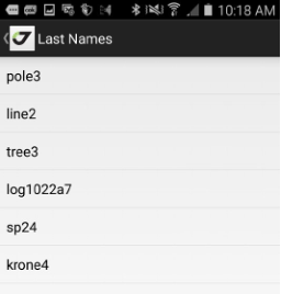
Figure 47. Last names screen
The button  near Description opens the screen with the last descriptions you used. You can use the same description without retyping it.
Ability of Site name, Description and Code controls on the screen can be controlled with check marks in Organize View screen depends on your workflow.

The button  allows taking a photo and attach it after surveying to the surveyed point.
The button  allows recording an audio comment and attach it after surveying to the surveyed point.
The information about the surveying is shown on the top: number of surveyed epochs and number of epochs to be surveyed (and number of rejected epochs), surveying time, and the line with coordinates. Below are summarized the survey details: occupation time, epoch filter and antenna model and height.
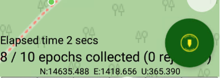
Figure 48. Text Information during surveying
3 lines of controls form survey controls –
- Configurable rectangles with arbitrary information
- Antenna height / type button and survey settings button
- Name, Code, Description edit controls
Two first control lines can be turned off / on in Orginize View dialog. Or just use swipe up and down gestures in survey text area to turn it on or off. The last Name/Code/Description controls can be configured to use or don’t use in the same Orginize View dialog. For example, if your workflow doesn’t use codes, you can turn off code controls.
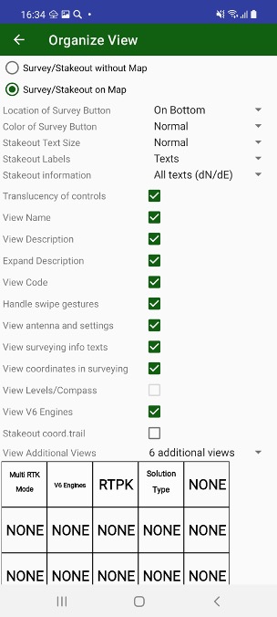
Figure . Orginize view dialog
Use View Name, View Description and View Code check boxes in this dialog to control visibility for Names, Description and Code controls.
The next line is antenna button and settings button.

Figure 49. Button with information about antenna
Antenna button shows antenna id and height. If slant height is used the height is finished with s suffix. For vertical antenna height vertical offset can follow after + sign. Click to the button opens Antenna dialog.
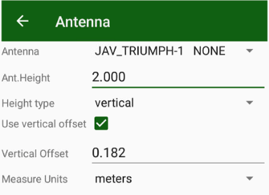
Figure 49. Antenna dialog
Vertical height is measured till ARP mark that is the screw on bottom for Triumph-1/M, Triumph-2 and Triumph-3. Because radio antenna is almost always set for Triumph-1/M, screw adapter for Triumph-2 and Triumph-3 for pole mounting, vertical offset is set in antenna. Radio antenna height is 0.182m, screw adapters for Triump-2 is 0.025m and for Triumph-3 is 0.03m. The values JMT sets automatically then antenna type is changed and Use vertical offset check box is set. If you don’t use vertical offset e.g. mount Triumph-2 to monopod set either vertical offset to 0 or check off the mark.
For slant antenna you can measure height from point to mark on receiver cover. E.g. for Triumph-2
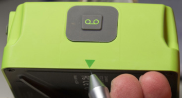
Near antenna button survey settings button is located.

Figure 50. Button with information about the survey settings
It shows current settings for survey / stakeout.
Tap on the bottom to see the survey settings:
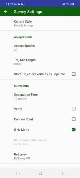
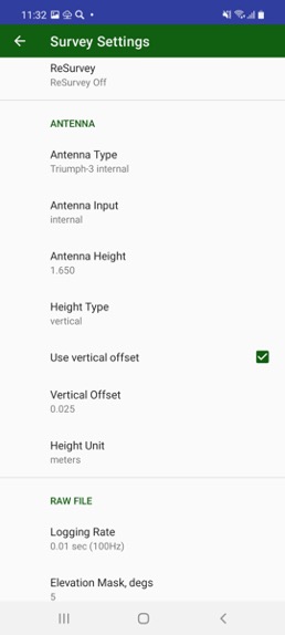
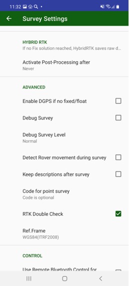
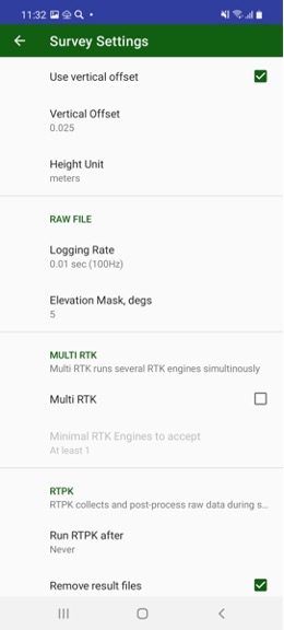
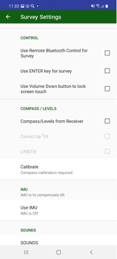
Figure 51. Survey settings screen
• • current setting style name; this let’s user create set of settings and quickly switch these sets of settings with one click
• Accept epoch filter - which epochs to use (All, Float and Fixed or Fixed Only), click shows more controls to set filter by HRMS, VRMS, PDOP, Height difference;
• Minimal trajectory length filter;
• Should Store trajectory vertices as points instead of trajectory vertices
• Occupation time (auto-completion time or “until stopped manually);
• Verify mode – activate verify mode surveying. In the mode for each point, JMT makes 3 surveys with 10 epochs with RTK reset after each survey. Then check is each survey result in 0.1m range. In the mode blunders are checked and that’s why result coordinates should be more robust but it takes more time for surveying.
• if you need point confirmation screen after each point survey. The confirmation screen shows all information about the surveyed point;
• 5 Hz mode – JMT collects 5 times more epoch. Your receiver should support 5Hz option in OAF;
• ReSurvey mode let’s you repeatly automatically survey.
• antenna input, model, height and height type with height offset;
• show vertical offset in dialogs option;
• receiver file name, logging rate and elevation mask;
• Hybrid RTK activation time (or Never to turn off)
• if you want to see DGPS solutions then neither Fixed nor Float positions computed;
• Multi RTK mode option. Then the mode is activated you can see 4 or 6 engines in surveying screen.
• Minimal number of RTK engines to accept. 2 or even 3 simulations fix engines are recommended to avoid blunders
• RTPK Mode activation time (or off/never)
• RTPK comparison mode (first fix used, compare both RTK and RTPK fixes or use only RTPK)
• Debug survey option. Turn it off till you need record a debug information for support
• Detect rover movement during survey mode
• If you want to keep description after surveying a point, otherwise it will be cleared.
• Does each point need Code or codes are optional;
• RTK Computation mode (Extrapolation or Delay)
• RTK Double check mode – improve RTK robustness but takes more resources
• if you want to use coordinate system transmitted from your VRS with RTCM 3.1 correction. In this mode, JMT will not get positions from standard WGS84 coordinates but lets receiver compute grid coordinate and JMT recomputes WGS84 using transformation of given coordinate system.
• compass and levels option. The option activates tilt compensation. Tilt compensation allows you to don’t use bubble on the pole and compensates pole inclination. But it decreases final accuracy up to 5 cm. Turn it off for precise works;
• calibrate levels and compass of your receiver;
• Lift&Tilt survey. The check mark enable Lift&Tilt surveying mode. In the mode you can control stop of surveying with just lifting pole with the receiver and start surveying just putting the pole vertically. So you don’t need touch receiver at all to do surveying.
• Ability to use external Bluetooth (e.g. paired selfi-stick) to start/stop survey
• Ability to use hardware keyboard Enter key to start/stop survey
• Ability to lock screen with Volume Down button (e.g. to clear water from screen)
• IMU survey (available only with Triumph-3 receiver). Opens dialog with IMU survey settings
• configure sounds in JMT.
• Sound configuration (two types of sounds available – beeps and voices)
Last line of controls includes 6 configurable elements which can show additional required information. Long click on each item lets select item from dialog:
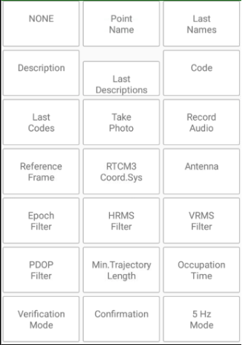
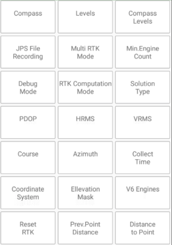

Clicking to such item also does item specific action, e.g set elevation mask, select position accuracy, activate/deactivate Multi RTK e.t.c.
This line can be turned on / off in Orginize View dialog or with up / down swipes.
¶ Point survey procedure
Standard point surveying (data collection) can be done with just pressing big green circle button. JMT starts collecting data by the pressing and stop automatically then required count of epochs will be collected. JMT shows progress in text like 2/10 (that means collected 2 epochs from total 10). Epochs for data collections can be filtered by solution type, by RMS or PDOP. If an epoch doesn’t fit selected criteria JMT rejects it and you can see in the progress text number of rejected epoch with their reason. Also JMT inform each epoch by sound – accepted epoch generates one sound, reject different one.
Surveyor can manually stop point surveying by pressing circle greed button again. That stops data collection and store point if any data has been collected.
After point surveying is over, JMT increment point name to be ready to survey next point by one click. Description of point also will be cleared to enable type new description and don’t let accept wrong description for the next point. If workflow requests use the same description for several points, you can turn off the behaviour of JMT by on check mark Keep Description after survey.
¶ Trajectory surveying
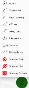
Long pressing big green circle button opens survey type selection. There surveyor can select Trajectory surveying or Fast Trajectory surveying. Pressing circle green button starts surveying, JMT collects epochs as trajectory vertices. The epochs can be filtered by type or RMS or PDOP, if an epoch doesn’t fit criteria the epoch will be rejected by JMT. Also minimal distance between vertexes can be set in survey settings, that helps you survey with any speed and then surveyor stays on a point no redundant data will be collected.
There exist setting that makes JMT stores points instead of vertexes. In that case JMT stores separate points instead one trajectory object with vertexes, that uses by default.
To stop survey a trajectory user click green circle button again. JMT stops data collection and increment trajectory name, to be ready start next one.
While surveying trajectory each epoch creates a vertex that immediately stored into job database. For Fast Trajectory JMT collects vertex data into memory to increase speed and reach 10 point per second rate. At trajectory finish all vertexes from memory are stored into job database, it takes time.
¶ Survey Result Confirmation
After surveying each point before storing into job database, JMT can show surveyed information and let the surveyor accept the point or resurvey it.
To enable this set check mark Confirm Point in survey settings. And after surveying the following dialog appears:
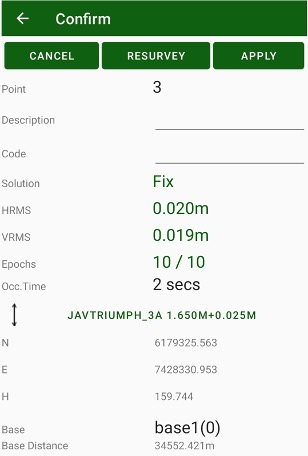
There surveyor can check result solution type and RMSes, type / correct description and code, see antenna and base information. If the data is OK, surveyor click Apply button and save the point. JMT will be ready to start survey next point. If something went wrong, surveyour can either cancel the point surveying or resurvey it again.
¶ Offset survey
Tapping the Offset button you will switch to Offset Survey mode. In this mode you can survey the unreachable points, i.e. line building corners, or trees where you can’t put the receiver antenna to survey the point. You can survey two intermediate points and measure the distances from them to the required point. JMT software computes the required point coordinates and stores them.
You can select from several type of offset tasks:
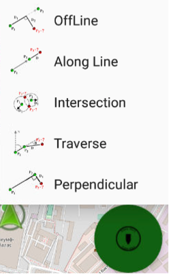
• OffLine offset: you define a line with two intermediate points and set two distances along the line and across the line to computed point.
• Along line: you define a line directed to computed point and you measure distance from the second point to computed.
• Intersection: you measure two distances from two intermediate point to computed point.
• Traverse: you define a line with two intermediate points and set angle and distance from the line to computed point.
• Perpendicular: you define a line with two intermediate points and just measure distance left or right from the line to computed point.
¶ Rangefinders
It is very useful to use a laser range-finder for offset survey. JMT allows connecting Bosh GLM50C, GLM100C, GLM120C or Leica Disto laser range finders to your Android device using Bluetooth. To connect a range finder use Rangefinder item from home screen.
You can select range-finder and connect it to Android device. After that in RTK Survey screen during offset survey, you can type in an edit box (e.g. Along, Offset, Distance, Distance2), then measure distance with the range-finder and press Bluetooth button on your range-finder. That transmits data from range-finder to Android device text box.
¶ Lift&Tilt survey
Activating “Lift&Tilt Survey” options you can do survey controlling pole lifting and tilting without pressing anything on a controller. You can do this with the receiver that has built-in levels – TRIUMPH-1M, TRIUMPH-2 and TRIUMPH-3. Use Compass/Levels option should be active to enable this.
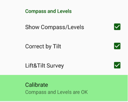
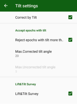
Then options set, surveying screen looks like this:
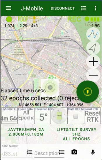
Figure 52. Lift&Tilt Survey
Tap the Lift&Tilt Survey Button to start the surveying. Now then you set pole with receiver vertically, JMT warns you with sound and starts surveying. JMT warns you with different sound enough data have collected. To finish survey just tilt pole with the receiver. JMT stores result. And every time you put receiver vertically JMT starts the survey and finish by tilting. To stop the mode, tap the Lift&Tilt Survey button again.
¶ IMU Surveying
Triumph-3 receiver has built-in Inertial Measurement Unit (IMU) that can compensate tilt of the receiver on pole. To work with IMU 100Hz OAF option should be purchased. Then working with IMU, surveyor sets pole with receiver on the point and tilt receiver on the pole and then do not move and wait till receiver computes reduced position. Fix solution should always be during surveying with IMU.
There are two scenarios of IMU surveying –
- Fixed tip and
- Moving tip
In the first scenario (Fixed tip) surveyor sets pole with receiver on the point, click Survey button and do not move till IMU initialized and Do not move message disappeared, swing pole till Moving message appears and then do not move pole till receiver compute result coordinate. All this time RTK fix solution should be in the receiver.
In the second scenario all actions in receiver can be in parallel with surveying, so surveyor can swing pole with receiver till he is moving to point and then just wait and do not move till receiver computes coordinate. So surveyor just puts pole with receiver into the point and press Survey button and wait till surveying is over. All this time RTK fix solution also should be in the receiver.
To activate IMU surveying just go to survey settings and click IMU item there. Following dialog appears:
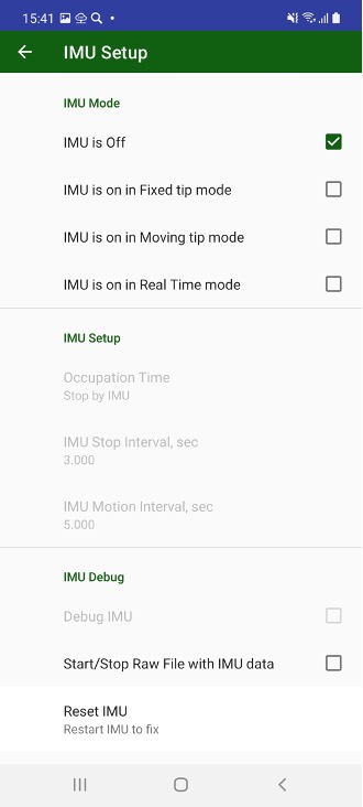
Set check mark for selected IMU mode. There are some other settings, but they are mostly useful in default values.
Reset IMU helps is any problems with IMU occurred.
For IMU surveying gyroscope and accelerometer inside your receiver should be calibrated. JMT checks the receiver and if required let you recalibrate device. Please read chapter about calibration.
¶ Surveying with RTPK
RTPK is another RTK engine inside the receiver. It uses different method of computation like post-processing software it collects data for minutes and then gives result. Triumph-3 and Omega are receivers those have RTPK feature inside. JMT can control RTPK inside the receivers. To activate RTPK goes into survey settings and select Run RTPK after list and set a period of time then RTPK will be run. It is recommended to set at least a minute.
Another RTPK setting is RTPK mode.
- RTPK can be used to get fix solution then RTPK can’t. This is First Fix mode. In the mode if RTK gives fix solution, the survey is over, otherwise if RTPK gives fix solution before RTK, RTPK solution will be used as result.
- Compare Both Fixes mode waits till both RTK and RTPK fix solution are ready and compares them. If a distance between RTK and RTPK solutions too large, the survey repeats.
- RTPK only mode wait till RTPK solution and stores it as result.
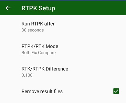
The first mode lets increase probability of fix and saves time. The second mode increase robustness of the result.
If RTPK is activate then surveyor starts a point, JMT starts data logging into second receiver file, and after given period of time RTPK will run and generates results. If the results is OK survey is over, JMT stops RTPK and remove result file and temporary raw data file. If the result is wrong, the data collection continues and RTPK will run again after the given period of time.
JMT shows information on RTPK status during surveying. It is useful also to add RTPK white box into surveying area.
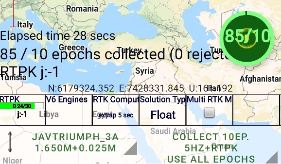
To work with RTPK OAF option should be purchased.
¶ Sounds during surveying
During working JMT can keep your attention with sounds. Then epoch is accepted one sound is played, then it is rejected other sound is playing, so surveyor can control surveying even without looking into display. The other actions like connection lost or solution type changes are played with special sounds. JMT has two predefined sound schemes – beeps and voices. The first one just sound and in the second scheme voice description of the action pronounced. Also each sound can be changed with user sound with sound settings dialog. It can be called from survey settings or from settings.
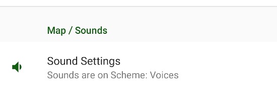
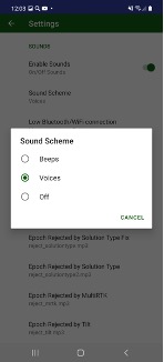
¶ Stakeout
With stakeout screens you can perform the points stakeout or stakeout along line or stakeout on surface.
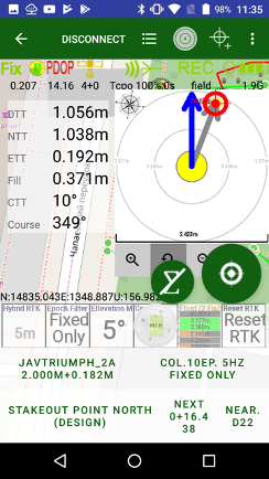
There are 3 stakeout modes supported with JMT:
- Point stakeout. JMT navigate to a selected point.
- Line Stakeout. Define line with two points and define a target with distances along/across the line. JMT navigate to this point and show distances along and across the line
- Surface Stakeout. Download surface either with triangles from DXF/DWG file or points from any standard import format and JMT build triangles from the points. JMT finds corresponding triangle and computes and show height difference in each point.
Stakeout screen includes 3 adjustable lines of stakeout controls – - Target button with Next and Nearest buttons
- Antenna and Stakeout/Survey settings buttons
- Additional view with customer selectable view
The controls can be configured with Orginize View dialog called from menu.
Under the controls, texts with coordinates and surveying process are located.
And two circle buttons. Big circle button does survey point by click and changes survey/stakeout mode with long click. Smaller button with sum sign let’s turn on/off averaging mode (see Average in Stakeout chapter)
In the left corner you can see your current coordinates in the current coordinate system. In the right corner several information values are displayed:
• DTT (distance to target);
• NTT (north distance to target);
• ETT (east distance to target);
• Cut or Fill (height distance with target);
• Course (your current course);
• CTT (course to target);
In the line stakeout mode, you can see two additional values:
• Forward or Backward (distance along line);
• Left or Right (distance across line).
Select a point with coordinate command or from list command or by tapping to a point and opening the stakeout menu item. Then select the Line command and define a line with two points, line stakeout mode will be used. And for Surface stakeout you set surface with either DXF/DWG file with triangles or file with points and JMT triangulate the points itself.
To set the target perform one of the following:
• Click to stakeout button on the bottom of the screen and select point from list of points or define line stakeout in Line Target dialog or select surface with Surface Target dialog;
• Tap to a point on the map, tap to i-icon and select Stake command;
• Select menu item and in position dialog type coordinates, use Cur.Pos button to set current position there
Then you use Line stakeout Select Line command and set line target. Line is defined either two points or one point and a direction and height difference. Then the line is defined you can set target position along and across the line.
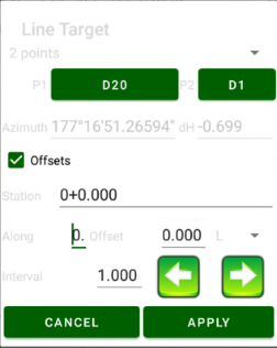
Figure 54. Line target
Then you use Surface stakeout Surface Target dialog is used. Surface is defined with triangles those can be imported from a file. Either triangles from DXF/DWG can be imported or any format with points can be imported and JMT triangulate them to triangles. Result triangulation are stored in triangles.txt inside your job. Then the surface is defined you can see height difference on the map.
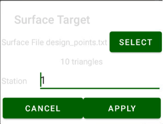
Figure 54. Surface target
Next button switch target to next point in the list that is not staked out yet. Nearest button finds nearest button in the list of points to current position that is not staked out yet.
You can see red line between your position and red target mark position. If the line stakeout mode is selected, you can see two points (1st for begin and 2nd for end) linked with a magenta line, which defines your target line and the target position defined related to the line. In surface stakeout mode you can see triangles and current triangle is marked in blue.
Your goal is to reach the target.
Also, there is “bull eye” control. This control shows your position with circle coloured with current solution type (green for fix, yellow for float and red for standalone) and your target with red crossed circle icon and points around them. Target and current position are connected with grey arrow. The line shows your direction to the target. Second blue line shows your current direction. Your task to match these two lines. Then you match the lines they changes color to green. And you can go this direction till reach target. In case then course-up mode is active, you just can set direction arrow to top.
To see bull-eye control. tap the menu item with circles. In this control you can see the circle (“bulls eye”). You can change scale in the bull eye with the zoom plus and minus buttons or press zoom button with arrow to let the software changes the scale automatically to keep target in the bull eye. Button with chevron-up arrow expand the “bull eye” control to all screen.
Your position or target position can be in the center of the screen. Tap to the center to switch to this mode. So then your position is in the center target is in the circle and then target positions in the center your position is in the circle. The grey arrow shows the direction from your position to the target.
The “bulls eye” map can be oriented to north (north up) or to your course (course up). The orientation can be changed by tapping to the orientation icon on the left top of the “bulls eye”. The blue arrow shows your course. You should coincide the two arrows to go to target.
In Surface stakeout mode the windows shows height difference in visual mode.
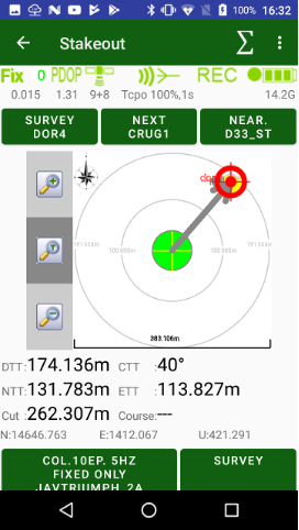
Figure 55. Stakeout with expanded bull-eye
On the bottom you can see the stakeout values like DTT, CTT, Course etc.,
and your current coordinates.
There are also two buttons on this screen: settings of the stakeout (antenna height, which epochs to use), and survey button.
There are several buttons on the top of the screen. One is to change stake-out target mode from the point to the line and vice versa. The second but- ton is used to set the target. The right button with arrow is used to switch to the next target point (works for both point and line mode).
For background map, you can use different variants. Select Map Provider from the menu to see the following dialog:
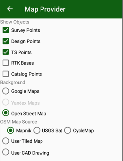
Figure 56. Map Provider
Here you can select as the background map either Google Map or Open Street Map or select your own background in the raster format User map Tiles created in MapTiles (.mbtiles) application or in JustinLink or vector CAD Drawing (DXF/DWG).
¶ Point Stakeout
For point stakeout you can select a position and JMT precisely navigates you to the position –target. The target can be selected from list of points (survey, design or catalog). Or clicked from map. Or read from receiver. Or typed manually
DTT (Distance to Target),
CTT (Course to Target)
NTT (North distance to target)
ETT (East distance to target)
Cut/Fill (height difference with Target)
¶ Alongline Stakeout
For along side stakeout user defines a line by two points or a point and direction. JMT shows your position along and across the line with additional info fields – Along and Across.
Also a target can be defined using two parameters – along the line and across the line. Then you stakeout the target all standard information (DTT, CTT, ETT, and NTT) are shown in addition to Along / Across information.
¶ Surface Stakeout
With stakeout on surface, JMT lets you download a surface – a file with either triangles (DWG/DXF format) or just points. Then points are downloaded, JMT triangulates them and builds triangle itself. With his surface triangles, JMT computes height in your position and compares the height with your current height. So you can see Cut or Fill values on each place.
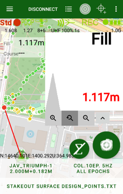
¶ Average in stakeout
There is smaller circle button with sum icon new main action button appears for stakeout.
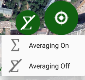
This button allows to stakeout maximum precisely. Long click to this button and select Averaging On to activates average mode. In this mode then you click the Average button JMT averages epochs and then freeze the screen to let you analyse data and select next movement of the receiver. During average the button changes colour from yellow to show progress. 
To turn off average mode long click the button again and select Averaging Off.
¶ Stakeout with Sun direction
JMT shows Sun icon on bulleye screen. So surveyor can orient himself with sun position. Clicking to sun icon surveyor can set Sun up orientation for the bulleye. In that case surveyor can rotate to sun or by his own shadow and see target position orientation.
Clicking to Sun icon on left up corner turn off Sun up mode.
¶ Position tail in Stakeout
JMT can show your previous positions tail inside stakeout bulleye control. The newer positions are darker, the older are visible worse. So you can orient yourself from your previous positions. To turn on / off the feature you can use Stakeout coord. trail checkbox in Organize view dialog.
¶ Visual Stakeout
With Triumph-3 receiver, Augment Reality stakeout (aka Visual Stakeout) is available in JMT. The feature is available only on controllers with AR support, list such devices is by the link:
https://developers.google.com/ar/devices.
Then the mode is available in menu you can see [AR] item. To do AR-stakeout do following:
- Setup your receiver as RTK rover and get stable fix solution.
- Select a point target for stakeout. Click AR item for Visual Stakeout.
- Initialize camera of your controller pointing it to a horizontal surface and move with your receiver several meters to initialize compass.
- You will see yellow cone of your target and blue line to it on your camera. Follow by the blue line direction to reach the target.

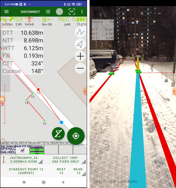
¶ CutSheet (stakeout report)
Then stakeout is done a stakeout report can be shown – CutSheet . Surveyor can go to list of points and select CutSheet item there, or using commands go to directly to CutSheet item. The following dialog appears:
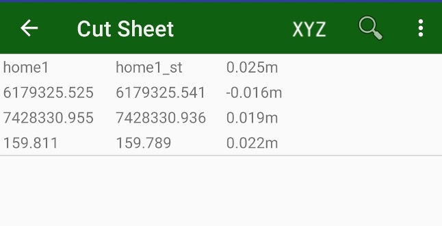
There surveyor can see list of staked point with their design name, surveyed name, coordinates and distances between design and survey positions.
The report can be exported in some formats using Export command from menu.
It is possible to see only plain coordinates and differences, switch between plain and 3D views and exports can be done with XYZ menu item. It will changed to XY then XY-only mode is selected.
¶ Import, Export and Report
¶ Import
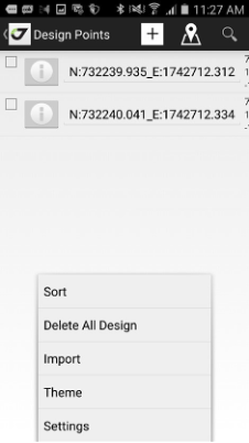
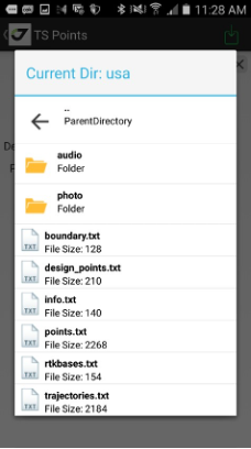
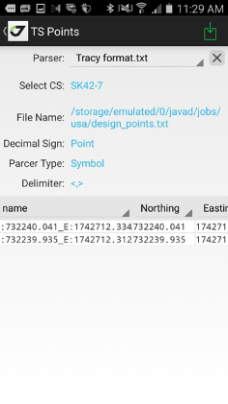
For the stakeout, you need to have the design points. You can type them manually, and alternatively, you can import them from a text file. JMT supports import different CAD/GIS formats as well as from user-defined text files. Switch to points, select Design points and select Import. Or use main screen and select Import action there. 
Import screen appears. Here you can select the file to be imported and define all file format parameters.
Then select file to be imported. There are two types of file browse dialog are supported – Javad (for internal storage) and System to access to shared storage.
Several formats can include different parameters screen, most of them are swap XY coordinate values and which objects to import – only points, points with lines or surface stakeout faces
The survey results can be exported to the user-defined text file, to CAD/GIS format (DXF, MapInfo, KML etc). Or you can use the Justin Link free desktop application to connect to JMT and download the data.
Also background drawings can be imported to JMT.
¶ Export to file
In the list of points select the points you want to export (or if you want to export all data don’t select anything at all). To select several points long click a point text and check marks appears.
To do export select Export menu item.
Otherwise, if you want to export everything, click Export item in main screen  or use Export from drawer menu.
At first select format in the following dialog and then set required parameters.
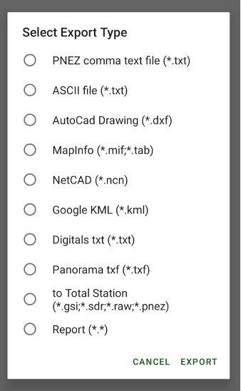
Files can be selected two types – Javad for access into internal storage or System for access into other folders.
Share after export check mark lets share the result file using all Android ability methods (e-mail, instant messengers etc).

These two variants:
| Javad ---|--- System |
| 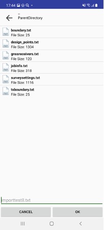 ---|---
 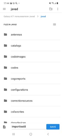 |
|
Different formats have different settings for export. Simples format is PNEZ, it does not ask anything parameters and output surveyed points into a comma-delimited file.
Other formats asks what to export to (only surveyed objects or surveyed + drawings). Most settings are in DXF file format:
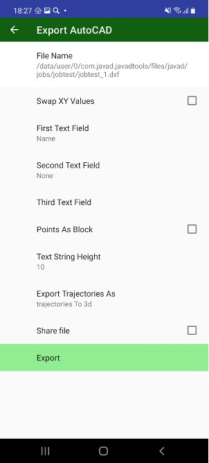
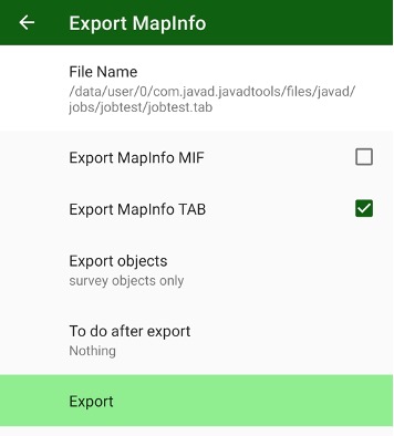
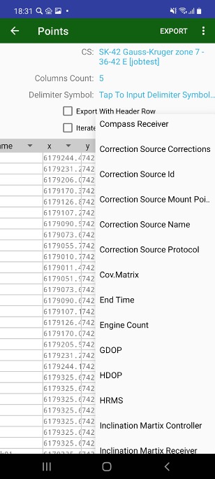
For custom text file you can define a format for export: number of columns, delimiter and columns data with the list headers. You can change the coordinate system. In that case, the JMT software writes coordinate recomputing on the file.
¶ Job Exchange
In addition to point exchange, JMT supports the exchange of jobs. You can click on a job and select Share Job command. Then you can choose a way to share the job – e-mail, Skype, Dropbox, OneDrive and all other exchange ways that your Android device supports.
You can exchange a job between two controllers with JMT on the same network. Click the menu button on the controller that is going to receive job and select Receive command. Receive Job dialog appears. There you can see the list of controllers with JMT. Click to any controller and list of jobs of the controller appears. Click on a job to receive it. JustinLink Exchange server should be turned on both controllers (in Services dialog).
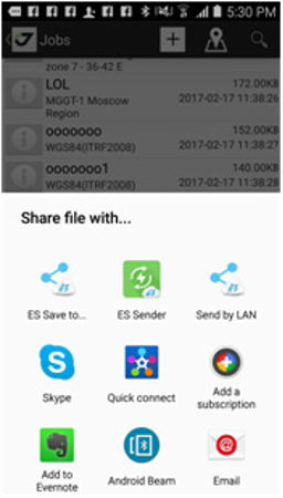
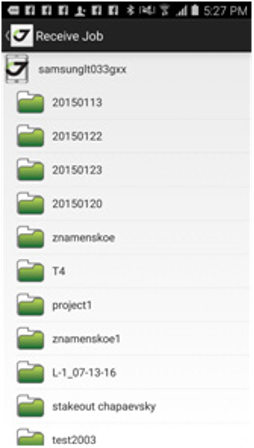
Figure 59. Share Job dialog Receive job dialog
The file will be created. All the data related to JMT is stored in javad subolder on device memory.
¶ Export to CAD/GIS formats
Then you select format for export. Then DXF format is selected you can select
What labels to add to each point. Up to 2 labels can be add. Also you can swap X and Y coordinates in the file.
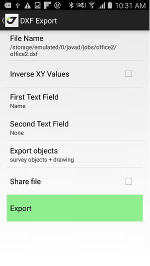
¶ Report
Result of surveying can be export in custom format, e.g. print out a Word document
In your own formating . For this you can use Report item in export. JMT provides
several predefined format, and you can create your own using the format files
as an example making its copy. Then you select Stimulsoft report template you can create your own report format using Stimulsoft report generator. There report consists of two parts - .rmt file, explain report format and .json file explain report data. You can create your own .rmt file and use .json data created with JMT to combine them to final report. JMT processes the data with a special server to generate the final report and to convert it to a selected format – PDF, Word, Excel, PowerPoint etc.
Final result report can be shared or opened in your Android device. It is stored by default in your job folder.
¶ Using JustinLink
JustinLink is a JAVAD free desktop application for exchange data with JAVAD mobile application like J-Field, Tracy and JMT. It can be downloaded it from JAVAd web site:
http://javad.com/jgnss/products/software/justinlink.html
Note: JAVAD’s Justin software includes JustinLink.
Run JustinLink or Justin and select this button on tool bar. The list of remote devices with their projects will be shown.
Note: The devices should be in the same network (local Ethernet or Wi-Fi network).
Select the project(s) you want to import and click the Import button. If you want to export the design points, you need to select the points in the JustinLink and by clicking New Project to create them or export to an ex- isting project.
¶ Export to Total Station
Many survey tasks may need be performed with Total Stations in combination with GPS. You can use the JMT software to export the GPS data to the Total Stations or import the Total Data measurements to the same job with GPS data.
You can convert your data to some formats for Total Station and export to a Total Station via Bluetooth connection.
Following formats are supported in this version:
• Leica GSI
• Sokkia SDR33
• Raw RW5
These are steps to send data to a total station.
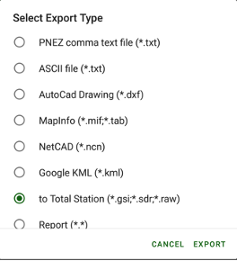
Select to Total Station item while export data
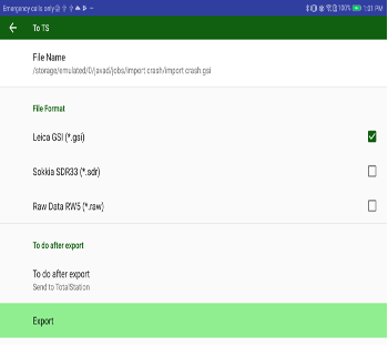
Select format you want to export to. And select Do after export.
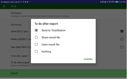
Select Send to Total Station. And press Export.
The exchange is available for total stations those support Bluetooth wireless technology. Otherwise, you can save the data to an USB Flash and connect it into to your Android device with JMT.
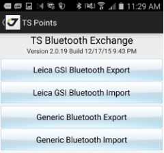
Figure 63. TS Bluetooth integration
Select Total Station item on home screen and Total Station Exchange screen appears. You can import and export data with generic text files which your total station supports or use the Leica GSI format to exchange the data with the Leica total stations.
¶ Data Exchange between controllers
With Exchange feature you can share information from one controller to another one. Jobs, points, survey settings, catalogs, correction sources, coordinate systems or just files.
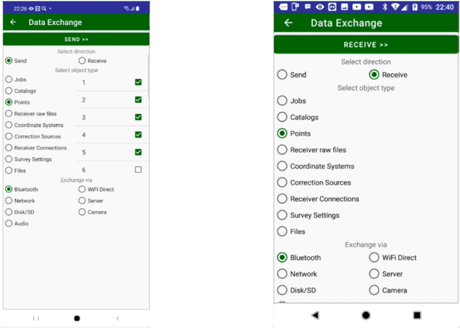
Then user enters Exchange dialog he selects will he send or receive the data with selecting appropriate radio button.
Then next group of radio buttons appears. There user can select:
- Jobs
- Catalogs
- Survey Points
- Design Points
- Receiver raw files
- Coordinate Systems
- Correction Sources
- Receiver connections
- Survey Settings
- Files
Then third block of radio buttons appears, there user can select method of exchange. He can use: - Bluetooth connection
- WiFi Direct connection
- Network exchange (devices in one network)
- Network Server
- Disk or SD card
- QR-Code with camera
- Audio
Then click to Send >> button to send to another controller or << Receive button to receive from other controller. Different sending/receiving methods show different exchange dialogs:

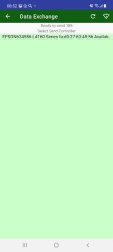
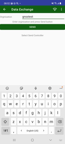
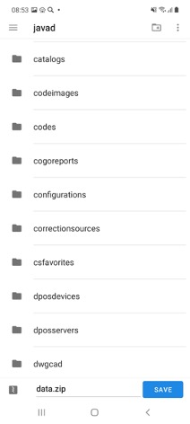
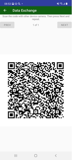
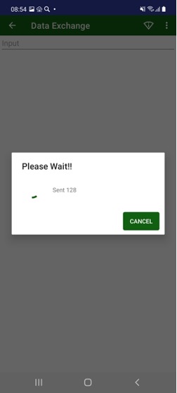
¶ Points
¶ Survey Points
All surveyed data you can see using List menu item or Point command from home screen. Here you can see different types of points - surveying points, design points, TS points, RTK Bases in the list and on the calendar.
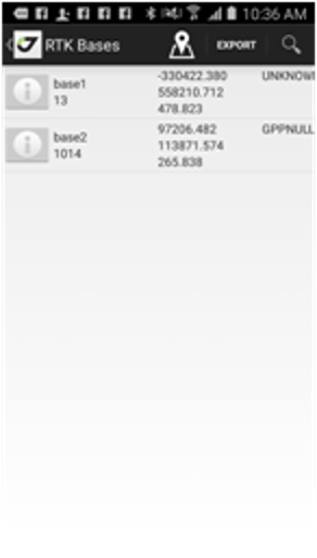
To switch between point types, you can use menu items.

S item to show Survey points
D item to show Design Points
T item to show Total Station points
R item to show RTK bases
Black menu item shows current selected point type.
On the list you can search and filter points by pressing Zoom button.
List can be rearranged with Sort button. You can use different sort variants – by name, by type, by time, by code, by comment (description).
In the list you can select points using Select menu item. In this mode check boxes appears near each item and you can select / unselect items. Select All and UnSelect All commands available for the mode in the menu.
Selected objects can be exported using Export menu item. If no items selected (no Select command performed) all points will be exported.
You can return back to map any time with Map menu item.
¶ Calendar
With Calendar menu item you can switch to calendar view for the points. Flag on a date with number shows number of points with this date.
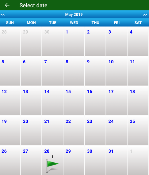
Click on the date opens point list with points filtered by this date.
¶ Contouring
In the map screen, JMT can build contours (isolines) map by surveyed points. To do this select Contouring command. The following dialog ap- pears. There you can set heights for the isolines. You can control to show triangles and unsmoothing isolines on the map.
Then you don’t need the isolines you can remove them by selecting the Contouring command again and Delete all contouring button there.
¶ Design Points
The same way you can see design points, the points for the stakeout. Use Design Points command from home screen to open Design Points dialog. You can see design points on the map and on the list. On the list, you can search and filter points by pressing Zoom button. Also, in the list, you can use different sort variants – by name, by type, by time, by code, by comment (description).
¶ RTK Bases
JMT stores RTK base information into job. Then a new RTK base information appears in receiver JMT adds it into RTK Bases Database. RTK Bases can be viewed with command RTK Bases from Home screen. Also, you can edit RTK Base coordinates or set/modify antenna height for the RTK base. That causes recomputation (move) of all rovers points surveyed from the RTK base.
¶ Total Station Points
JMT stores special points read from Total Station files – Total Stations Stations and Total Station Points. The points can be import from a Total Station with Bluetooth.
¶ CoGo (Computation Geometry)
Computation geometry routines let you do mathematical computation to produce new points or to obtain values like distances, area etc.
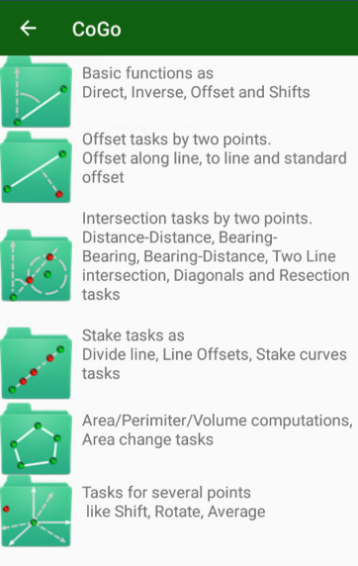
There are 6 group of CoGo tasks –
There are 6 group of CoGo tasks –
- Base tasks
1.1. Direct
1.2. Inverse
1.3. Traverse - Offset tasks
2.1. General Offset
2.2. Along-line Offset - Intersection tasks
3.1. Distance-Distance intersection
3.2. Two Line intersection (by 4 points)
3.3. Diagonal intersection (by 4 points)
3.4. Three Distance from three points intersection
3.5. Intersection of two perpendicular lines defined by 3 points - Stake tasks
4.1. Divide line task
4.2. Divide line with offsets
4.3. Stakeout curve
4.4. 3 Point Arc computation - Area/Perimiter/Volume
5.1. Area/Perimeter
5.2. Volume
5.3. Recompute area by moving hinge
5.4. Recompute are by moving edge
5.5. Compute parameters of triangle - Several points tasks
6.1. Move point by dN,dE,dH
6.2. Move points by distance and angle
6.3. Move points by angle around a point
6.4. Compute average coordinates of set of points
6.5. Compute isolines
Then you do a CoGo task corresponding dialog appears. There you can set points by pressing buttons and type values into edit boxes. And on the bottom of the screen Create button is located and you can type name for new point.
E.g. for Direct task

you can press P1 button to select point from list of points or from map. Then type Bearing into B editbox and Distance into editbox and dH into dH editbox. Pressing B button can switch between B, Grid and B, Magnetic values. Pressing D button you can select between D, Horizontal and D, Slant. Pressing dH button you can select between dH, dH Slope %, dH Angle and H Absolute.
Below picture of the task and result coordinates near it.
Create button and editbox to type name for new design result point. Then you press it next dialog appears:
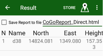
There you can set check mark to save text report into html report.
Pressing  menu item open map with data for this task.
Press Store menu item to create new design point and finish the task.
¶ Codes
Codes allow the user to share control points between jobs without typing them each time after a new job creation (or without importing them from a file). To operate with the control points use the following dialog
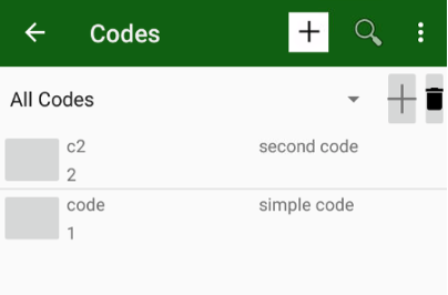
- button is used to add new code
Code includes Name, Description and Number. You can type them in the Code dialog

Code can have attributes (fields). To add a field to attribute fill Field values - Name, Type, Def. Value and range values. A field can be following type – String, Integer, Number and List.
For String type you can set maximum length of string.
For Integer and Number you can set minimum and maximum value
For list you can type list values.
Press Add button to add new field to the code.
On the left part you can see list of fields for the code. Click on it to edit. Click on it and select Delete button to delete the field.
Then the code is created you can press Apply to store the Code.
Codes can have signs. For this put small png images to javad/codesigns folder. Name of the image file (without extension) should be the same as name of the code.
Codes can be imported and exported from/to several data dictionary formats.

The codes are created you can assign code for surveying objects. Turn on Codes controls with View Codes item in Orginize View dialog . Then you can either type code or use code dialog for fast select code.
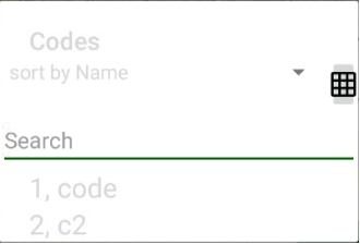
There you just start type code letters and JMT shows codes math the typed text
And you can select appropriate code by click.
Another way to select is to use Grid control. In that mode codes will be shown in grid and you can select them by just clicking.
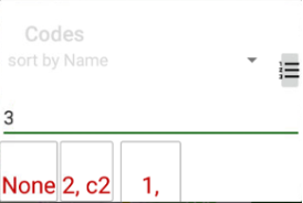
¶ Radio setup
All radio specific tolls are located in the separate screen. Tap the Radio icon on the home screen. It includes the following items:
• Pair radio;
• Repeater;
• Radio Firmware Loader.
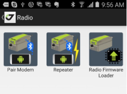
Figure 64. Radio
¶ Pair radio
The Pair radio command allows pairing a Bluetooth equipped radio with your GNSS receiver or unpair them. JAVAD Receiver with Bluetooth (TRIUMPH-1/M, TRIUMPH-2, or Sigma) can be paired with UHF or FH radios with built-in Bluetooth (HPTxxxBT devices).
To connect the receiver and the radio, the devices should be paired with Bluetooth. After that at powering they will exchange data via Bluetooth only with each other.
Note: The HPT radio could not be connected via Bluetooth with any other Bluetooth
device. Only the receiver controls the radio.
To connect the radio to another JAVAD receiver, check if the radio is un- paired with the previous receiver. After that, the radio can be paired with another receiver.
The JMT software allows unpairing the radios paired to the receiver and it can pair the unpaired radio to the receiver. The software should be con- nected to this receiver.
Note: For all other situations (to unpair radio without a receiver connected, or pair it with another receiver) you can use JAVAD Pair HPT Radio application. This application runs on Android devices with USB and uses the USB and serial connection to control the
radio. Download it for free using the following link: https://play.google.com/ store/apps/details?id=com.javad.pairmodem_usb
¶ Repeater
The external JAVAD UHF radios can operate in the repeater mode. In this mode you extend the range of your radio transmission with additional re- peater radio. It receives the corrections from the base and retransmits them to the rover. To use the radio in such mode, the base radio, rover radios and repeater should be configured properly. For base and rover radios the Repeater check mark should be set in correction source settings.
To configure repeater radio you can use Repeater command from the home screen. Repeater screen appears. There you can connect with Bluetooth to the repeater radio and JMT will set it as repeater.
Note: Base, repeater, and rover radios should have the similar configuration parameters for the proper work.
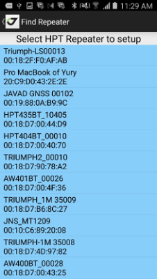
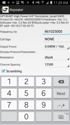
Figure 65. Repeater screen
¶ Radio firmware update
You can update the firmware of the HPTxxx or HPTxxxBT radios con- nected via Bluetooth.
Note: The radio should be unpaired to be accessible with Bluetooth or you should be
connected to the receiver paired with the radio.
Tap the Update Firmware command and Update HPT firmware screen
appears. Select the radio:
• unpaired Bluetooth radio;
• radio paired to current receiver;
• this receiver internal radio.
Find the radio and select the firmware file. JMT shows appropriate devices and firmware version of the file and if everything is correct downloads the firmware into the radio.
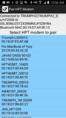
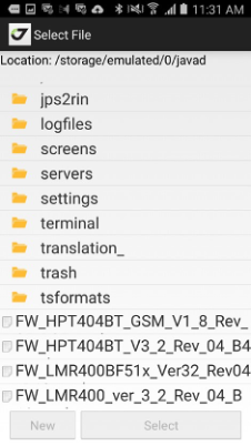
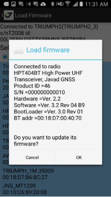
Figure 66. Firmware loading
Note: More reliable way to update HPT radio firmware is to use an USB connection and special application: Javad Radio Firmware Loaded. Download it for free using follow- ing link: https://play.google.com/store/apps/details?id=com.javad.
firmwarehpt_usb
Note: Also you can use NetView desktop application to update the radio firmware with USB or serial cable.
¶ Compass and level calibration, Gyroscope calibration
TRIUMPH-3 has internal gyroscope and inclinometer, TRIUMPH-2 and TRIUMPH-1M receivers have internal compass and levels. That helps you several ways - for stakeout you can see direction even when you don’t move, for surveying your receiver corrects its inclination (you don’t have to constantly see the bubbles because compass and levels correct the inclination).To operate correctly compass and levels should be calibrated. You can use the JMT software to calibrate the internal compass and levels for T2, T1M and internal inclinometer and gyroscopy.
Select Calibrate item on the home screen, Calibration screen appears.
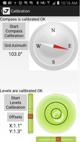
Figure 67. Calibration
It shows the status of compass and levels and allows calibrating compass and levels and adjusting levels offsets with Offsets button.
¶ Compass calibration
Compass calibration starts by tapping the Start Compass Calibration but- ton. For compass calibration you should rotate the receiver for all axes for one minute. The screen shows recommended rotation types.
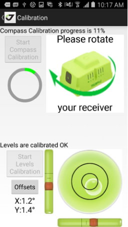
Figure 68. Compass calibration
¶ Levels calibration
For level calibration you need to place the receiver on the flat horizontal surface. The screen shows which side should be up. To start calibration tap Start Levels Calibration button. Image with receiver orientation appears. Set the receiver like depicted and tap Start Side Calibration button.
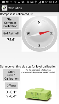
Figure 69. Level calibration
Don’t move or shake receiver for the one minute. The same way the next side will be calibrated. When all sides are calibrated the levels calibration is over.
¶ Removing Levels Offsets
If you don’t need for any reason the full calibration of levels, and you see the level value offsets (displayed in X: and Y: texts) when the receiver is in the flat horizontal surface, tap Offset button and level offsets will be set to zero.
¶ Gyroscope calibration
Triumph-3 IMU work requests calibrated gyroscope. To calibrate gyroscope just put receiver into flat surface, go to Calibration, press Start Gyroscope Calibration and don’t touch it till the calibration is over (about a minute).
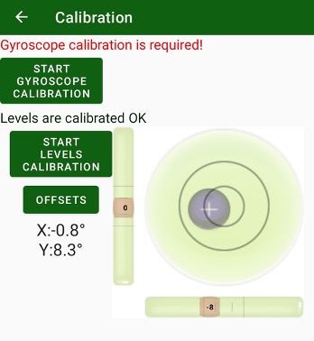
¶ J-Tip
The item let’s utilize ability of J-Tip accessory. J-Tip is a JAVAD GNSS’s magnetic locator. J-Tip screen on JMT lets produce sound for searching magnetic marks/tips.
At first a screen to connect to J-Tip with Bluetooth appears. After JMT connects to a device, next screen appears. There you can control gain and sensitivity of the device.
¶ Quadro / Duo
The item is used to setup SIGMA receiver with Quatro and Duo boards. For other devices the item is unavailable.
¶ Low level commands (Terminal)
For the extended control of your receiver the Terminal can be used. With Terminal you can send the GREISS commands and see the answers. Terminal is able to send the script files with several commands and log commands/answers to log files.

Figure 70. Terminal
Note: The detailed description of receiver commands you can see in the GREIS Reference Guide http://www.javad.com/downloads/javadgnss/manu-als/GREIS/GREIS_Reference_Guide.pdf
¶ Receiver control
For low-level receiver actions like reset, clean to factory default, update firmware and options you can use Control icon on the main screen. The following screen appears:
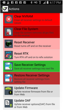
Figure 71. Actions
In the dialog you can perform the following:
• Clear NVRAM to reset all receiver settings to factory default;
• Clear File System to format file system and remove all receiver raw jps files;
• Reset receiver – automatically turns off and on the receiver;
• Save Receiver Settings – saves all receiver settings into text file. It
format is the same as NetView uses.
• Restore Receiver Settings – restores receiver settings from text file of settings. The file can be created with Save receiver Settings command in JMT or with NetView.
• Update firmware – replaces firmware for the receiver either from file
or from Internet.
• Update OAF – updates receiver authorization options (OAF) from file
or Internet.
¶ Update receiver firmware
Receiver’s firmware can be updated from a file or via Internet.
Select Update from File item and select the firmware file. If the firmware is suitable to the receiver model and has the newer version, file uploading will be started.
Select Update from Internet. There are two variants of firmware: Stable version to load the last stable firmware or Last version to load the last available firmware. Both versions are available on JAVAD website.
After the firmware file is downloaded from the site, the file uploading will
be started.
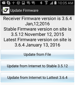
Figure 72. Update Firmware
Update receiver options (OAF)
If you have limited access to some abilities of JAVAD GNSS receiver you may need to update your OAF (Options Authorization File). By default, receiver options are disabled so you have to take special measures to activate them. It can be done by uploading an Option Authorization File (OAF) to the receiver from the local store or via Internet.
Tap the Update from file button and select .jpo or .opt file. The file name must correspond to the receiver identifier. Uploading the options from the file is happening the same way as via Internet.
Tap the Update from Internet button to upload options from Internet and
confirm the intention.
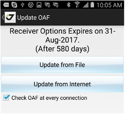
Figure 73. Update OAF
To check and update your options use the Update OAF command. After
Options are uploaded, receiver NVRAM is cleared and then receiver is reset. Note: For the complete description of the supported options see the GREIS Reference Guide http://www.javad.com/downloads/javadgnss/manuals/
GREIS/GREIS_Reference_Guide.pdf
¶ Services
There are several services which work in a background. They can be stopped or configured using the Services item from home screen. The following dialog with pages appears by tapping the command.
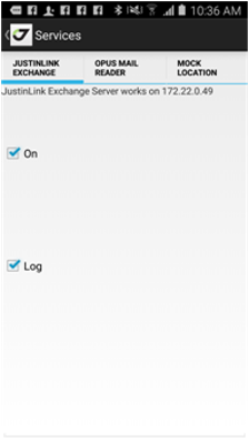
Enables start/stop ser- vice for JustinLink exchange. This service lets a computer with JustinLink to connect the Android device on the same Wi-Fi net- work with the computer.
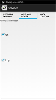
Enables start / stop e-mail service that reads the answers from NGS OPUS.
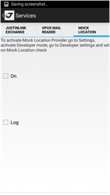
This page enables the replace of the Android position with the position from JAVAD receiver. The position can be used in other Android applications like CAD/GIS software.
¶ Wizard
JMT software has many possibilities. To help the user to be familiar with the software the Wizard is designed: a light application to setup everything for RTK Base. Starting Wizard you will see the initial screen; you can select the type of work (Post-Processing data collection, RTK Survey or RTK Stakeout).
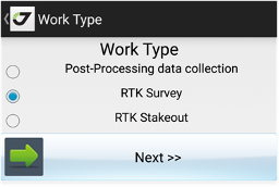
Figure 75. Wizard
Follow the on-screen instructions to set up the receiver using Wizard.
¶ Debug
JMT let’s you debug your equipment collecting raw data and collecting JMT related debug data. The tasks can be used separately or the can be combined. To turn on collecting raw data file with wrapped corrections from rtk base, user can go to RTK Rover and click file logging button and set check marks Receiver File Logging and Store Base Corrections, click back and start rover. The file will be started to collect. Then user can stop the data logging with stopping rover and then download the file and share with support.
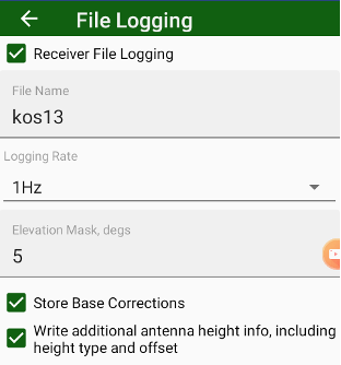
Other debug information is related to application itself. To activate recording the data user during surveying can go to survey settings and set Debug Survey check mark. JMT starts records text debug information into job folder into debugsurvey.txt file. The file can be shared with JAVAD GNSS developers to find and fix issues. The recording of
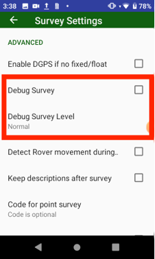
To combine all the data for maximum support Debug mode can be activated from settings. Go to Settings screen and scroll down to and. Click Debug, debug dialog appears. There you can set all required check mark and click Start Debug to start collecting debug information. Then do work to reproduce issue. Return back to Debug screen and click Stop Debug and Send Debug or Stop and Send Debug button. The screen switches to file manager and starts download raw data, then all the job will zipped and shared any standard Android way like e-mail or instant messenger.
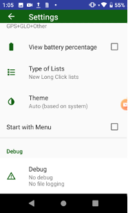
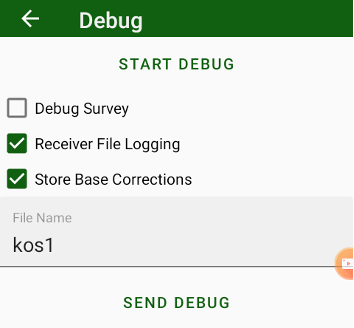
¶ Startup Resets
If your JMT constantly crashes at start up a resets available. Hold down volume down physical button (or down arrow button for Victor-2) while JMT starting. A reset menu appears.
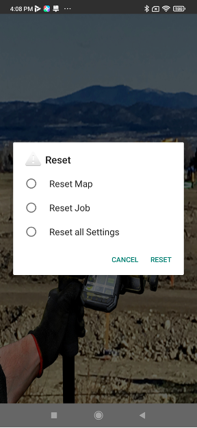
There are several resets available:
- Reset map. Reset map of current job to Google or OSM map.
- Reset Job. Reset current job to new job.
- Reset all Settings. Reset all settings.
Set check mark and press Reset to do reset. To cancel reset select Cancel.
¶ Dealer map
With JMT surveyor can find JAVAD GNSS dealer in area he is. Dealer Map item helps to do this.

¶ User manual
The JMT software has a built-in user manual. it can be downloaded using the command from the Home screen. The manual will be storing on your Android device and you can read it without Internet access next time.
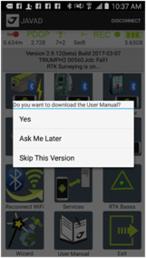
Figure 76. Manual
¶ Exit
To exit JMT you can use the Exit command from the Home screen. The following dialog appears
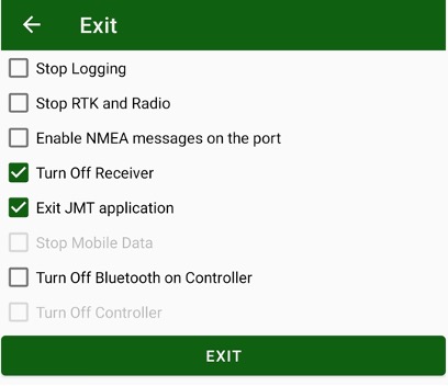
Figure 77. Exit
You can set check marks:
• Stop Logging – to stop logging to receiver raw data file and close it at exit, if any.
• Stop RTK and Radios – to turn off radios and switch receiver from RTK mode at exit.
• Enable NMEA messages on the port – enable NMEA messages to port connected to, with this scenario 3rd part software using NMEA messages (like ArcPad or other) can be connected to the Bluetooth port and work with your receiver
• Turn Off Receiver – turn off receiver at exit.
• Exit JMT application – is a mandatory item.
• Stop Mobile data – turn off Mobile data using (it is available only for Nautiz X8 device)
• Turn Off Bluetooth on controller – to save power JMT can turn off Bluetooth after using
• Turn off controller – turn off controller at exit (it is available only for Nautiz X8 device).

900 Rock Avenue, San Jose, CA 95131, USA
Phone: +1(408)770-1770
Fax : +1(408)770-1799
www.javad.com
All rights reserved © JAVAD GNSS, Inc., 2022