¶ Introduction
To convert the coordinates obtained by the satellite data (GNSS) processing from WGS-84 to a local coordinate system, it is important to have:
- Reference coordinates in local coordinate system.
- Coordinate transformations which connect this coordinate system with WGS-84.
The order, in which coordinates are calculated, is shown on the following chart:
Transformation of geocentric coordinate systems is performed by the formula of 7 parametric Helmert transforms:
and are WGS-84 geocentric coordinates and reference coordinate system accordingly ( - Source, - Target );
are translations along the axes ;
- is the scale factor. . The size of - is indicated in the list of datum Justin parameters in ppm, which means parts per millionths
In rotation matrix , where
are angles between axes of source and target coordinate systems. Axes are counted in the clockwise direction.
The formula of inverse transformation:
The Helmert transformation is a similarity transform in which the scale factor is the same for each coordinate. Combination of 7 parameters for transformation and ellipsoid is called datum. In the list of Justin datums the signs of parameters correspond to the transition from WGS 84 to the reference system.
Example.
Calculation of geodetic coordinates ( — latitude, — longitude, — height) with the use of geocentric coordinates (item 2 of the transformation scheme) is performed by iterations using the formulas:
- is the radius of curvature of the first vertical, - is the square of the first eccentricity of the ellipsoid. The reverse transition to rectangular coordinates from geodetic coordinates (stage 2 of the transformation scheme) - is described by the formulas:
where - is eccentricity and - is the radius of curvature of the first vertical.
To calculate geodetic coordinates, there is need to specify an ellipsoid - semi-major axis and eccentricity.
The transformation of geodetic coordinates into rectangular coordinates on a plane is performed based on the type and parameters of the map projection. The transition from geodetic (ellipsoidal) height, which is measured along the normal to the ellipsoid, to orthometric height is performed by the formula:
where - is the height of the geoid above the ellipsoid.
Geoid heights are determined from geodetic coordinates based on a geoid model that is defined relative to the same ellipsoid for which the geodetic height is calculated.
Stage 4 of the transformation scheme is performed between two rectangular coordinate systems specified on the plane. Finding the parameters of such a transformation in geodesy is usually called localization or calibration.
Planned transformation formulas are similar to stage 1.
where
The formulas are:
where are offsets along the coordinate axes.
are Northing and Easting are rectangular coordinates on a plane. - is the turning angle, counted clockwise. - is the scale factor.
The formula for inverse transformation for coordinates on a plane:
The formula of altitude transformation:
- is height in the original coordinate system, - is height increment, are slope angles along the Northing, Easting axes.
The determination of the transformation parameters of coordinate systems on the plane is performed by the ordinary least mean squares method (LMS) by comparing the resulting transformation chain 1 — 4 and the original (from the catalog) coordinates of the points.
The parameters of the horizontal and vertical transformation are calculated independently. The minimum number of points required for calculation is two points for plane localization and three points for vertical localization.
Local datum includes 4 parameters of plane transformation plus 3 parameters of vertical transformation. Sometimes, this set of parameters is called 4+3 datum. This highlights the difference between it and datum with 7 parameters, which is used for calculation of geocentric coordinates transformations.
¶ New
The calculation of the transformation parameters of rectangular coordinate systems on a plane and vertical coordinate systems is performed in the Localization window.
To activate this window, open Coordinate system manager by select the main menu item Program, then Coordinate systems (or click the icon  ). In the opened window click the icon
  and choose Localization
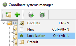
Figure 18-1. Program Coordinate systems Localization
¶ Open
To open previous saved local coordinate system right click in Coordinate system manager and select Localization:
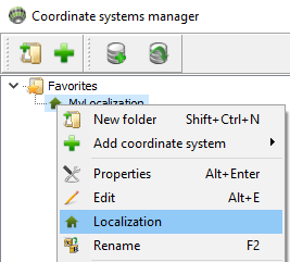
Figure 18-1a. Program Coordinate systems Localization
Menu Localization will appear only when you click over local coordinate systems
¶ Icon bar
The bar of icons functionally corresponds to all localization commands.
![]()
Figure 18-3. The bar of icons
Icons provide the following functions:
| Icon | Description |
|---|---|
 |
save new localization |
 |
save localization as… |
 |
import txt files by template, *.jl files, Sites and Reference points coordinates |
 |
export txt files by template and *.jl files |
 |
perform localization calculation |
 |
restore the default table settings (column width, number of displayed decimal places, etc.) |
 |
activate / deactivate a bookmark, which contains a list of calculated parameters of horizontal and vertical transformations |
 |
add columns to enter estimates of the accuracy of the coordinates of points |
|
add a new row to the end of the table |
 |
add a new row to the table before the selected one |
 |
remove selected row from table |
 |
delete all rows in table |
 |
set the width of the column in which the cursor is located, according to the maximum cell length in this column (including the heading) |
¶ Save
By clicking or buttons save localization in a program database.
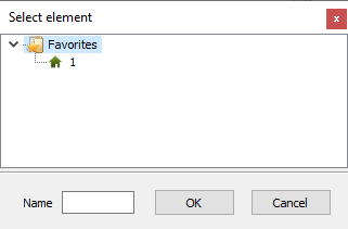
Figure 18-1b. Save localization
Select folder and enter name of local coordinate system and press OK button.
Not only transformation parameters are saved but all table data also. It is possible to save unprocessed table data.
¶ Main window
The main elements of the Localization window are the bar of icons, the settings panel and the coordinate entry table:
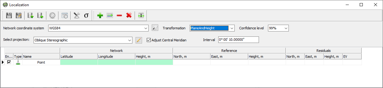
Figure 18-2. Localization window
¶ Data table
The data table is used to display the coordinates of points and to estimate the accuracy of the transformation calculation. Accuracy estimation is based on residuals. It depends both on the coordinate quality of the satellite network points and the mutual consistency of the reference points, and on the reliability of the user-specified projection parameters of the local coordinate system of the Reference. The columns of the table are combined into blocks — Network, Reference, Residuals. The Network block contains coordinates of points in the selected coordinate system. As a rule, these are the coordinates of points obtained from adjusting of the free GNSS network. Reference block — coordinates of points in the local rectangular coordinate system on the plane. The residuals obtained from adjustment are shown in the right part of the table.

Figure 18-3. Titles of the data table
In the input window, each line contains information about one item and contains the following columns:
| Column | Description |
|---|---|
| Enable | the selected check-box means that the coordinates of the point will be used when calculating the parameters. Otherwise, the point is excluded from the calculation process. In this case, the corresponding row in the table is shaded, residuals are not calculated. |
| Type | sets the type of transformations in which a specific item can be used. Double click on cell will appeared menu: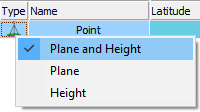 Figure 18-4. Item type selection It is possible to set one of three types of tying to control points:
|
| Name | item name |
| Latitude, Longitude, Height | from the Network block — coordinates of points in the reference coordinate system. Depending on the type of coordinates which were entered into these columns (ellipsoidal or rectangular on a plane), there may be options BLH or North / East). |
| North, East, Height | from the Reference block — coordinates of points in the local coordinate system. |
| EV | residuals of points of the coordinates by the corresponding component and residuals by radius vector. |
 - Plane and Height. The coordinates of the points will be used to calculate the parameters for the horizontal transformation (Latitude / Longitude or North / East) and the vertical transformation (Height)
 - Plane. The coordinates of the points will be used to calculate the parameters for the horizontal transformation (Latitude / Longitude or North / East)
 - Height. The coordinates of the points will be used to calculate the parameters of the vertical transformation (Height)
¶ Working with table
For greater clarity and convenience of work, the table uses color highlighting of fields. The coordinate columns of points in the original coordinate system are highlighted in green. The fields of the residual columns (except for the EV column) are highlighted in red before the parameters are calculated. After calculating the parameters, the fields of these columns can be marked in green if the corresponding corrections to the measurements meet the criteria for the -test (tau test), or in red if the test is not passed. During the -test, the correspondence of corrections to the coordinates of points to the estimate of their accuracy obtained from the adjustment is analyzed. Therefore, sometimes, even relatively small corrections can be marked as not passed the -test. In addition to the -test, it is important to pay attention to the magnitude of the residuals, while evaluating the results of localization.
If the item is excluded from the calculations (the check-box in the Enable column is unchecked), the color of the corresponding line changes to pale green. Fields for the value of the corresponding residuals will be empty and will be highlighted in white.
To edit the type, names, coordinates of points directly in the table, double-click the corresponding field with the left mouse button. To save the editor in the text information input columns, press Enter, or by pressing the left mouse button, move the cursor from the edited field.
Empty fields in the Height column are not highlighted in another color. The height value for this item will not be considered when calculating the altitude transformation parameters. The corresponding field in the residual columns is highlighted in the line by white color:
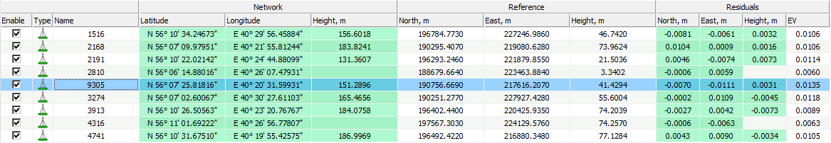
Figure 18-5. Data in the Height column
When the coordinates are entered in the table in the columns of the Network block and there is no value of any planned coordinate (deleted from the table by the operator, omitted in the imported file), then the input line is not taken into account in the calculation (site 1516). The result will be similar to deleting item information from the table or unchecking the check-box in the Enable column). The discrepancies of the row will be zero, and their fields in the table are highlighted in white:
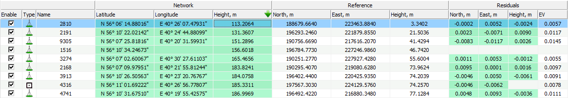
Figure 18-6. Missing data in the field
When changing the type of a point, those coordinates that do not belong to this type are excluded from the calculations. The fields in the Residuals columns are highlighted in white. For example, site 4316 does not use elevation, and site 1536 does not use plane coordinates.
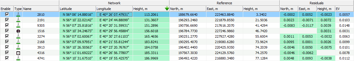
Figure 18-7. Item type
Similar rules apply to coordinate columns of the Reference block.
Fields in which coordinates are not entered (for all three columns) remain empty, and when importing a file with a coordinate value missing in the corresponding input template, a message is displayed indicating the line number in which it is absent or incorrect data is given:
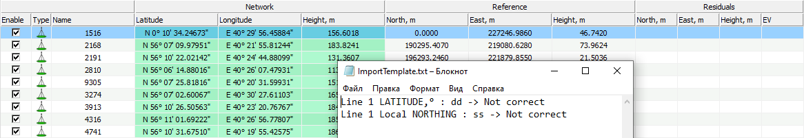
Figure 18-8. Input error message
Window with the message can be closed. Then it is possible to manually enter the known coordinate value or leave the field blank.
¶ Parameters
In addition to the coordinate table, a tab can be activated bookmark with calculated localization parameters.
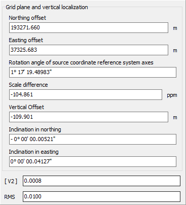
Figure 18-9. Localization parameters bookmark
- North and East offsets, Rotation, Scale - four parameters of the plane transformation (if calculated) are displayed
- Vertical offeset, North and East inclinations - three parameters of the vertical transformation (if calculated)
- [ V2 ] - sum of the squares of the residuals (by the radius vector, the Input table section, the description of the Residuals column)
- RMS - mean square error.
¶ Settings
The settings panel is designed to select various settings and parameters when calculating conversion parameters.

Figure 18-10. Settings panel
¶ Network coordinates
The Network coordinates drop-down list is used to define the type of coordinate system for the coordinates that will be imported into the Network block:
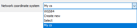
Figure 18-11. Selecting the coordinate type
These can be ellipsoidal (BLH) coordinates (set by default), or rectangular coordinates on a plane (GRID). Depending on the selected type of coordinate system, the table view is configured, settings for the coordinate input template are selected (section Importing coordinates into a table).
Since the main purpose of the Localization module is to tie the coordinates of global satellite navigation systems – WGS-84, obtained as a result of processing / post-processing by the Justin program — to ground points, then, mainly, the coordinates of the Network essentially denote the coordinates of WGS-84. In this case, the BLH / Grid switch only affects the external representation of coordinates since the internal representation of the data in the Justin database is WGS-84.
The situation is different when importing grid coordinates from a file, in which coordinates can be specified in any form. Setting the switch allows you to correctly identify the original data, that is, convert it to the internal representation of the WGS-84 program. The list of coordinate systems offered for selection corresponds to the list available in Coordinate system manager.
The reference coordinate system is characterized by a map projection and a global (spatial) 7-parameter datum. The purpose of localization is to calculate the parameters of the local datum required for transformations of coordinates specified on the plane.
The local datum is used in the Justin program in addition to the global one, but its calculation may be of interest for use in independent coordinate transformation programs. The parameters of the map projection are not subject to calculation (except for the value of the axial meridian, for those projections where it is available).
The accuracy of the conversion to local coordinates depends on the accuracy of the initial definition of the coordinate system of the Reference. The dependence of the accuracy of transformations on the parameters of the global datum is relatively small. In most cases, the main source of calculation errors is the inaccuracy of the choice of the central meridian. Distortions in the coordinates of the item increase with distance from it. Therefore, the parameters of the cartographic projection of a predefined coordinate system of the Reference should be as accurate as possible correspond to the real, which are not always known. It is possible to recommend the selection of parameters and type of cartographic projection of the Reference to achieve the best result.
If nothing is known about the type and parameters of the cartographic projection of the Reference coordinate system, then in the drop-down list of coordinate systems you should select Oblique Stereographic, which is equivalent to choosing a stereographic projection with a central point calculated as the average between their maximum and minimum values of latitudes and longitudes for points of the Network block, zero shifts along the axes and unit scale.
¶ Transformation
The Transformation drop-down list is used to define a set of calculated parameters: Plane (set by default) – 4 parameters of the horizontal transformation are calculated, Height — three parameters of the vertical transformation, Plane + Height — four parameters of the horizontal and three parameters of the vertical transformation, Offsets only — 2 parameters of the horizontal transformation (shifts along the North and East axes). In this case, the roll angle is 0, the scale is 1.
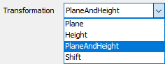
Figure 18-12. Choice of transformation
¶ Auto select CM
The Autoselect CM check-box is designed to select the Central Meridian when calculating transformation parameters.

Figure 18-13. The Autoselect CM checkbox
If the check-box is not selected, the coordinates of the Grid points are converted to the Reference coordinate system using the preset value of the Central Meridian, specified by the map projection in the Select projection list of coordinate systems. If the check-box is checked, the meridian is automatically selected for the six-degree zone with the boundaries shifted by 3 degrees to the left and right relative to the average longitude of the points of the Network block. The calculation is performed in a cycle with a longitude step equal to the entered value in the Interval field (the preset step value is 10 seconds). The criterion is the estimate of the sum of the squares of the residuals. The value of this sum is reflected in field [V2] of Localization parameters bookmark (Figure 18-9). The value of the central meridian, for which the transformation parameters were obtained, can be viewed by clicking the button  :
:
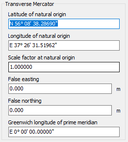
Figure 18-14. Plane system parameters for translation into the Reference coordinate system
The values of these parameters are updated after each calculation of localization with the Auto-select CM check-box checked or at any time can be changed manually in this window. If the Autoselect CM check-box is not selected, the values of these parameters are entered only manually and do not change during the calculation.
In the course of calculations, the longitude step, the value of the current central meridian for which the
calculations are being performed, the value of the central meridian for which the best estimate of the localization accuracy has been obtained at the moment and the sum of the residual squares are displayed in the Progress window with a progress bar with the Auto-select CM check-box selected:
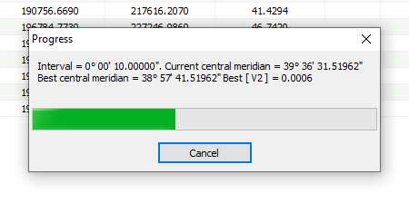
Figure 18-15. Progress window
¶ Confidence interval
Confidence intervals are set to searching blunders with -test.
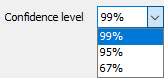
Figure 18-16. Choosing a Confidence Interval
The 95% confidence level corresponds to a narrower confidence interval, that is, the criterion for passing the test will be more stringent. 99% confidence level corresponds more wide error interval.